


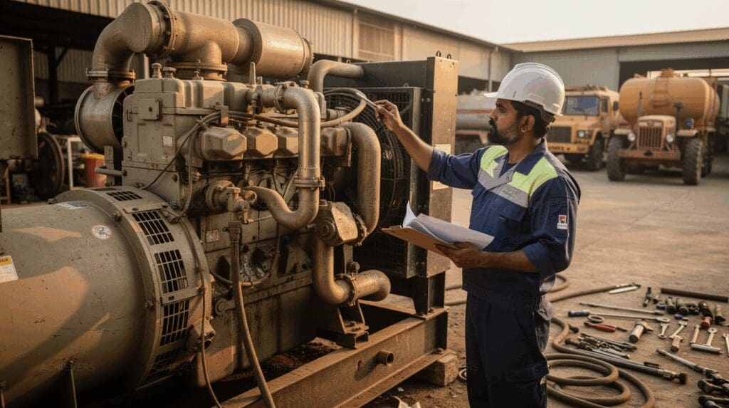
For your diesel engine, fuel used equals fuel supplied minus fuel returned. Choose CE-121 if you need stock fuel on the display; choose the Diesel Generator / Vehicle Engine Flow Meter if its engine-rating sensor table and fuel-used-with-time display fit your records.
How the meter calculates diesel used
A diesel consumption meter calculates fuel used by subtracting return-line flow from supply-line flow. CE-121 uses two separate sensors: one measures fuel entering the engine, and the other measures fuel returning. Its calculator shows in-flow, out-flow and used fuel.
> Supply path: Fuel supply → input sensor → engine
> Return path: Engine → return sensor → fuel return
> Calculation: Input sensor reading − return sensor reading = fuel used
The engine flow meter also shows fuel supplied, fuel returned and fuel used. Its display adds time to the fuel-use reading. If your records rely on consumption, use the fuel-used figure rather than the supply figure.
CE-121 sensors carry a pulse-per-litre value on each sensor body. That value links sensor pulses to the fuel quantity shown by the calculator. CE-121 sensors are calibrated with pure diesel at 0.5, 4 and 25 bar.
Calibration covers 25%, 50%, 75% and 100% of the flow range at those pressures. For your installation, check the value on each sensor and the calculator setting if the readings need review.
Compare the two diesel consumption meters
CE-121 shows stock fuel; the engine flow meter shows fuel used with time. Their stated accuracy figures match, so choose by sensor fit, supply, display and output.
| Meter | Sensor | Power | Display | Optional output | Accuracy in standard installation position |
|---|---|---|---|---|---|
| CE-121 | Positive displacement | 220V AC, 12V DC or 24V DC | In-flow, out-flow, used fuel, stock fuel; backlit | RS-485 Modbus | ±1% RS or 0.1% FSD |
| Diesel Generator / Vehicle Engine Flow Meter | Oval gear | 5–24 VDC; onboard supply 8–30 VDC | In-flow, out-flow and fuel used in litres with time | RS-485 or RS-232 | ±1% RS or 0.1% FSD |
Both meters are described for diesel engines. CE-121 is also described for diesel generators, while the engine flow meter covers generator and vehicle applications.
Neither accuracy figure makes one meter the more accurate choice on its own. The standard installation position is a condition of both figures; check it against your planned sensor position.
Choose CE-121 when your operator needs stock fuel beside supply, return and use. Choose the engine flow meter when a fuel-used reading with time suits your monitoring record. Those display choices do not settle sensor size, which needs a separate check.
Match the engine power band to a sensor model
For the engine flow meter, models 006 through 025 match the power bands below. Use this mapping only for that product, and give the rating unit shown on your engine.
| Engine flow meter sensor | Engine power band |
|---|---|
| 006 | Up to 200 KW/KVA/HP |
| 008 | 200–400 KW/KVA/HP |
| 012 | 400–800 KW/KVA/HP |
| 015 | 800–1000 KW/KVA/HP |
| 020 | 1000–1500 KW/KVA/HP |
| 025 | 1500–2000 KW/KVA/HP |
CE-121 uses CE-121-006 through CE-121-025 variant names, but select them by the exact connection and flow requirements. Its engine-rating bands do not give a clear match to individual CE-121 variants. Do not carry the engine flow meter’s rating table across because the suffixes look alike.
| CE-121 sensor model | Thread size |
|---|---|
| CE-121-006 | 1/4 inch |
| CE-121-008 | 3/8 inch |
| CE-121-012 | 1/2 inch |
| CE-121-015 | 1/2 inch |
| CE-121-020 | 3/4 inch |
| CE-121-025 | 1 inch |
The two 1/2-inch CE-121 variants make thread size alone an incomplete selection rule. For your CE-121 choice, provide the engine rating, expected fuel flow and both line connections. Check which exact sensor variant fits those details before installation.
Check power, display and output before selecting
Match your available supply to the meter, then choose the display and optional output your team will use. CE-121 accepts 220V AC, 12V DC or 24V DC.
The engine flow meter gives 5–24 VDC as device power and 8–30 VDC as its onboard vehicle supply range. If your vehicle supply exceeds 24 VDC, clarify how those two engine-meter power figures apply before wiring it.
- For a local reading: CE-121 shows stock fuel with in-flow, out-flow and used fuel. The engine flow meter shows fuel used in litres with time.
- For remote records: Specify optional RS-485 Modbus for CE-121. For the engine flow meter, specify optional RS-485 or RS-232 to match your monitoring input.
- For sensor fit: Record the engine rating and its unit, expected fuel flow, and supply and return connections. Use the engine meter’s rating table only for its 006–025 sensors.
- For the accuracy check: Record the planned sensor position. Both ±1% RS or 0.1% FSD figures refer to the standard installation position.
If a reading changes after installation, the fuel consumption meter maintenance checks cover accuracy drift, air issues and RS-485 faults.
FAQs
Which diesel fuel consumption meter is most accurate for tracking usage?
Both meters give ±1% RS or 0.1% FSD in the standard installation position. Neither has a better stated figure; check sensor fit and installation position for your engine.
What’s the best engine fuel flow meter for monitoring generator or vehicle consumption?
Choose the engine flow meter if its 006–025 rating table and fuel-used-with-time display fit your setup. Choose CE-121 if your team needs stock fuel beside supply, return and use.
Does the CE-121 show fuel remaining in stock?
Yes. CE-121 shows stock fuel alongside in-flow, out-flow and used fuel on its backlit display.
Can these meters provide data output?
Yes, as options. CE-121 offers RS-485 Modbus; the engine flow meter offers RS-485 or RS-232. Specify the output your monitoring system accepts.
Quick pick
- CE-121: Choose it for a stock-fuel display and 220V AC, 12V DC or 24V DC supply options.
- Engine flow meter: Use its 006–025 engine-rating table and fuel-used-with-time display to assess fit.
- Either meter: Check your supply, both fuel-line connections and the standard sensor position.
- Before selecting: Give your team the engine rating, expected flow and required optional output.
