When industrial procurement teams and plant managers invest in fluid dispensing infrastructure, the expectation is straightforward: precise volume, consistent repeatability, and zero unscheduled downtime. However, achieving this predictable outcome depends entirely on the metering technology at the heart of your Liquid Batching System. For most industrial applications—ranging from automotive assembly lines dispensing transmission fluids to automated chemical packaging—the decision ultimately comes down to two dominant flow measurement technologies: the oval gear meter and the turbine meter.
Understanding the fundamental engineering differences between these two mechanisms is critical. Selecting the wrong meter type for your fluid's viscosity or your plant's flow profile will lead to erratic batch volumes, product giveaway, and premature equipment failure. This consultative guide breaks down the physical operating principles, accuracy stability, lifecycle costs, and maintenance requirements of both technologies to help you specify the right Liquid Batching System for your global operations.
Quick ROI Snapshot
- Typical payback period: 12 to 18 months.
- Primary ROI drivers: Elimination of product giveaway (achieving ±0.2% accuracy), reduction in manual dispensing labor, and minimized maintenance downtime.
- Long-term savings: Properly matched positive displacement systems can save thousands of dollars annually by preventing over-dispensing of high-value lubricants and transmission fluids.
1. Overview of Liquid Batching System Family
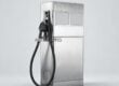
A Liquid Batching System is an integrated, automated skid or assembly designed to deliver a precise, pre-programmed volume of fluid into a vessel, vehicle, or process line. Rather than relying on operator judgement, these systems utilize a closed-loop control architecture to guarantee exact dispensing.
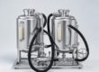
At a fundamental level, an Achievers system is engineered with several core components that work in continuous harmony:
- The Pump: Provides the necessary kinetic energy and pressure head to move the fluid from the bulk tank to the dispensing point.
- The Flow Sensor (Meter): The critical measurement device (such as an oval gear or turbine) that translates fluid motion into a quantifiable electrical signal.
- The Controller: The programmable brain that receives pulses from the flow sensor, calculates the accumulated volume, and compares it to the target batch size.
- The Solenoid Valve: A fast-acting automated valve that opens to initiate flow and snaps shut the millisecond the controller registers that the precise batch volume has been achieved.
When configuring these systems, the most impactful engineering choice is the flow sensor.
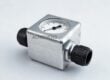
Oval Gear Meters (Positive Displacement):
Oval gear meters operate by trapping isolated pockets of fluid between two interlocking, oval-shaped gears and the meter casing. As fluid pressure pushes the gears, they rotate, passing precise, discrete volumes of liquid with every revolution. Magnets embedded in the rotors trigger a sensor, sending pulses to the controller. Because this is a volumetric measurement, it is largely immune to changes in fluid viscosity or flow profile disturbances.
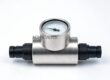
Turbine Meters (Inferential Measurement):
Turbine meters feature a multi-bladed rotor suspended in the flow stream. As fluid passes through the meter body, it imparts a rotational force on the blades. The rotational velocity of the turbine is proportional to the velocity of the fluid. A magnetic pickup detects the passing blades and sends pulses to the controller. Because it relies on fluid velocity to infer volume, turbine accuracy is heavily dependent on a consistent flow profile and is highly sensitive to changes in fluid viscosity.
Pre-Purchase Data Checklist
Before evaluating meter types, ensure you have defined the following parameters for your site:
- [ ] Minimum, normal, and maximum flow rates (e.g., 60 Litre/Min).
- [ ] Fluid viscosity at the lowest operating temperature.
- [ ] System operating pressure and allowable pressure drop.
- [ ] Target accuracy requirements (e.g., ±0.2% for critical dispensing).
- [ ] Available power sources (e.g., 220 V AC).
2. Head-to-Head Specification Comparison
To make an informed, data-driven decision, we must look at how these technologies perform across standard industrial specifications. The following table compares a high-precision Oval Gear Liquid Batching System against a standard Turbine Meter alternative, utilizing verified performance data.
| Technical Specification / Feature | Oval Gear Meter System | Turbine Meter System |
| :— | :— | :— |
| Operating Principle | Positive Displacement (Volumetric) | Inferential (Velocity-based) |
| Standard Accuracy | ±0.2 % | ±0.5 % to ±1.0 % |
| Viscosity Handling | Excellent (Improves with higher viscosity) | Poor (K-factor shifts significantly) |
| Typical Flow Capacity | 60 Litre/Min (Standard Achievers Model) | Varies (Typically higher flow ranges) |
| Power Source | 220 V AC | 220 V AC or 24 V DC |
| Straight Pipe Requirement | None (Immune to flow disturbances) | Minimum 10x upstream, 5x downstream |
| Pressure Drop | Moderate to High (Increases with viscosity) | Low (Minimal flow restriction) |
| Erosion Resistance | High (Robust metallic gears) | Moderate (Blades susceptible to wear) |
| Best Target Application | Motor oils, diesel, transmission fluids | Water, light solvents, low-viscosity chemicals |
3. Application Comparison Table
Theoretical specifications only tell half the story. The true test of a Liquid Batching System is how it behaves under specific, often harsh, plant conditions. Selecting the right technology requires matching the physics of the meter to the realities of your fluid.
| Application Scenario | Recommended Option | Engineering Reasoning |
| :— | :— | :— |
| High Viscosity Fluids (Motor Oil) | Oval Gear | High viscosity reduces slippage between gears, actually increasing the accuracy of positive displacement meters. |
| Automotive Assembly Lube Dispensing | Oval Gear | Requires exact ±0.2% precision to meet strict vehicle manufacturing tolerances and avoid overfilling. |
| High-Speed Bulk Water Transfer | Turbine Meter | Water lacks lubricity and has very low viscosity; turbines handle this efficiently with minimal pressure drop. |
| Space-Constrained Installations | Oval Gear | Requires absolutely zero straight pipe runs upstream or downstream, allowing for compact skid design. |
| Variable Flow Rate Batching | Oval Gear | Maintains linear accuracy across a massive turndown ratio, even as flow ramps up or trails off. |
| Diesel Oil Batching | Oval Gear | Diesel provides excellent natural lubrication for the gears, ensuring brilliant execution and long lifecycle. |
| Corrosive Light Fluids | Turbine Meter | Can be easily manufactured from exotic alloys or plastics to resist chemical attack from thin solvents. |
| Pulsating Flow Conditions | Oval Gear | Physically traps and measures fluid volume, meaning pump pulsations do not distort the flow reading. |
Common Mistake to Avoid
Installing a turbine meter for lubricating oils or transmission fluids is a costly engineering error. As fluid viscosity changes with ambient plant temperatures (thicker in the morning, thinner in the afternoon), the drag on the turbine blades changes. This causes the meter's K-factor to shift unpredictably, destroying your batch accuracy and leading to massive product giveaway over time. Always use positive displacement for viscous liquids.
4. Total Cost Comparison
Procurement teams must evaluate fluid handling investments through the lens of Total Cost of Ownership (TCO), not just the initial capital expenditure. While one technology may seem cheaper off the shelf, the maintenance burdens and accuracy deviations can drastically alter the actual financial impact over a 10-year lifespan.
| Cost Variable | Oval Gear System | Turbine Meter System |
| :— | :— | :— |
| Initial Purchase Range (USD) | $$ – $$$ | $ – $$ |
| Installation Costs | Low (Drop-in installation, compact) | Moderate (Requires piping modifications for straight runs) |
| Annual Maintenance Effort | Low (Periodic inspection of gears/bearings) | Moderate (Frequent recalibration needed as bearings wear) |
| Product Giveaway Cost | Negligible (Strict ±0.2% accuracy prevents waste) | High (Viscosity shifts can lead to 1-2% over-dispensing) |
| Expected Lifecycle | 10 to 15+ years (in lubricating fluids) | 5 to 8 years (Bearing and rotor wear limit lifespan) |
| Best ROI Case | Dispensing high-value lubricants, oils, diesel | Bulk transferring low-value water or thin solvents |
For facilities handling costly petrochemicals, a high-precision Oil Flow Meters integrated into a batching system pays for itself rapidly. A 1% error on a turbine meter dispensing thousands of liters of synthetic transmission fluid daily equates to substantial financial losses that far outweigh the initial savings of the cheaper meter.
5. Decision Guide: Which One for Your Plant?
To finalize your specification, work through this step-by-step decision matrix. By evaluating your process demands against these eight operational scenarios, you can confidently select a system that guarantees high endurance, high effectiveness, and minimal support requirements.
- Assess Fluid Viscosity and Lubricity:
- Evaluate Accuracy Mandates:
- Review Installation Geometry:
- Analyze Power and Integration Needs:
- Determine Flow Profile Stability:
- Calculate Allowable Pressure Drop:
- Consider Plant Temperature Fluctuations:
- Evaluate Long-Term Maintenance Capacity:
If you are handling diesel oil, motor oil, or transmission fluids, you must select the Oval Gear system. These liquids provide natural lubrication to the interlocking gears, minimizing wear and maximizing operational life. Furthermore, their high thickness prevents fluid bypass (slippage) inside the measuring chamber, locking in the ±0.2% accuracy.
If your facility requires exact custody transfer precision or is filling consumer-facing products where strict volume laws apply, default to Oval Gear. The mechanical isolation of fluid pockets ensures that precisely 60 Litres pass per minute, regardless of downstream backpressure variations.
Analyze the physical footprint of your piping infrastructure. Turbine meters require fully developed, laminar flow to function correctly. This typically dictates a straight pipe run of at least 10 pipe diameters upstream and 5 downstream. If you are building a compact mobile skid or retrofitting a tight assembly line, the Oval Gear meter is mandatory, as it acts as a flow conditioner itself and requires zero straight runs.
Ensure your site can support the required electrical infrastructure. Achievers systems are robustly designed to operate on a standard 220 V AC power source, making them easily integratable into existing plant grids without requiring specialized low-voltage DC transformers.
If your system utilizes a positive displacement pump (like a gear or diaphragm pump), it will naturally generate flow pulsations. Turbine meters read these pulsations as velocity spikes, severely skewing the batch total. Oval gear meters physically trap the fluid, making them entirely immune to pulsating flow dynamics.
If your system operates strictly on gravity feed with minimal head pressure, you must carefully calculate pressure loss. Oval gear meters require fluid energy to physically turn the mechanical gears, creating a noticeable pressure drop. If your pressure budget is practically zero, and the fluid is water-like, a turbine meter might be the necessary compromise.
Does your plant experience significant temperature swings between summer and winter, or even day and night? Temperature inversely affects fluid viscosity. A turbine meter calibrated for oil at 40 degrees Celsius will be wildly inaccurate when dispensing that same oil at 15 degrees Celsius. Oval gear meters ignore these viscosity shifts, delivering consistent batching year-round.
If your maintenance team is already stretched thin, prioritize positive displacement. When used in lubricating applications like Diesel Flow Meter integration, oval gears suffer virtually zero friction wear. Turbines, conversely, rely on delicate thrust bearings that inevitably wear down, requiring frequent recalibration and eventual rotor replacement.
FAQ
Q: Why does the Achievers Liquid Batching System specify a ±0.2% accuracy?
A: This stringent accuracy tolerance is achieved by utilizing precision-machined oval gear technology. Unlike velocity-based meters, the interlocking gears provide a true volumetric measurement, ensuring that variations in pump pressure or fluid thickness do not alter the dispensed volume, making it ideal for critical automotive and industrial filling.
Q: Can this system handle highly viscous transmission fluids?
A: Yes, absolutely. The system is specifically engineered to handle motor oils and transmission liquids with maximum thickness. In fact, higher viscosity liquids actually improve the volumetric efficiency of the oval gear meter by sealing the microscopic clearances between the gears and the casing.
Q: Do I need to install a flow conditioner upstream of the batching system?
A: No. Because the system utilizes an oval gear flow meter, it is completely immune to velocity profile distortions, swirl, or asymmetric flow caused by elbows, valves, or pumps. You can install it in tight, complex piping configurations without requiring straight pipe runs.
Q: What is the standard capacity of the Achievers batching setup?
A: The standard specified model offers a capacity of 60 Litres/Min. This optimal flow rate balances rapid batch completion with the precision control required to ensure the solenoid valve closes exactly on the target volume without hydraulic shock (water hammer).
Q: How often does the meter require recalibration?
A: When dispensing clean, lubricating fluids like diesel or motor oil, mechanical wear on the oval gears is exceptionally low. Most industrial facilities find that the meter maintains its ±0.2% accuracy for years, requiring only standard annual verification checks rather than continuous recalibration.
Q: Is the system fully automated, or does it require manual valve operation?
A: It is fully automated. The system integrates the meter, a programmable controller, and a fast-acting solenoid valve. The operator simply inputs the desired variable preset volume, and the controller manages the pump activation and precise valve closure automatically.
Q: What power source is required to operate the batching controller and valve?
A: The standard system is designed to operate on a highly accessible 220 V AC power source, ensuring seamless integration into typical industrial electrical grids without the need for complex power conversion equipment.
Ready to eliminate product giveaway and automate your fluid dispensing processes? Contact the engineering team at Achievers Pumps and Valves today to configure a Liquid Batching System tailored to your exact requirements. Please provide your target flow capacity, fluid viscosity, and site operating conditions, and our specialists will design a highly accurate, erosion-resistant solution that delivers immediate ROI for your operations.