Measurement drift in fluid handling is not just a maintenance inconvenience; it is a direct leak in your operational budget. Whether you are managing high-volume mineral oil transfers in a European petrochemical plant, lubricating systems in a Middle Eastern power generation facility, or hydraulic fluids on an offshore platform, accuracy is non-negotiable. Unplanned failure of your Oil Flow Meters leads to batching errors, unexpected downtime, and significant financial losses due to unrecorded product transfer.
Quick ROI Snapshot
- Typical payback period for rigorous preventive maintenance: 3 to 6 months.
- Direct cost savings: Up to 1.5% of total fluid transfer value recovered annually by preventing accuracy drift.
- Downtime reduction: Drops unplanned emergency maintenance interventions by 85%.
A proactive oil flow meters preventive maintenance schedule for industrial fuel transfer is your best defense against sticking rotors, pressure drops, and seal degradation. This guide provides plant managers, industrial engineers, and maintenance heads with a comprehensive strategy to maintain these critical volumetric instruments across diverse, harsh operating conditions.
1. Product Overview and Critical Wear Components
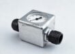
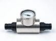
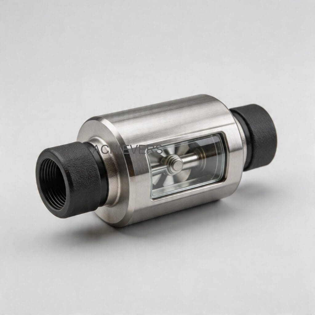
The core of high-accuracy Oil Flow Meters relies on a precision-engineered oval gear design. These are volumetric flow estimation instruments that measure flow by passing an exact, discrete volume of liquid with every rotation. Because the internal moving parts are dynamically secured in tandem with the volume of fluid traveling through the chamber, they maintain accurate metering over long periods of operation.
However, because the measurement relies on physical movement and tight mechanical clearances, these meters are susceptible to wear from particulate contamination, extreme fluid temperatures, and chemical abrasion.
Understanding the technical specifications helps dictate the maintenance requirements:
| Specification | Technical Detail | Maintenance Implication |
| — | — | — |
| Line Size Range | 006mm to 150mm (1/4" to 6") | Larger line sizes require heavy-duty lifting equipment for flange removal during deep inspection. |
| Repeatability | Better than 0.02% | Requires pristine oval gear edges; any particulate scoring will immediately degrade this spec. |
| Pressure Drop | Low weight/pressure drop | Sudden increases in differential pressure indicate strainer blockages or bearing friction. |
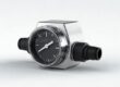
| Display Reading | Register cap rotates every 90º | Ensures easy visibility, but O-rings under the cap must be checked for weather ingress. |
| Filtration | Integrated mesh strainer | First line of defense; requires the highest frequency of preventive cleaning. |
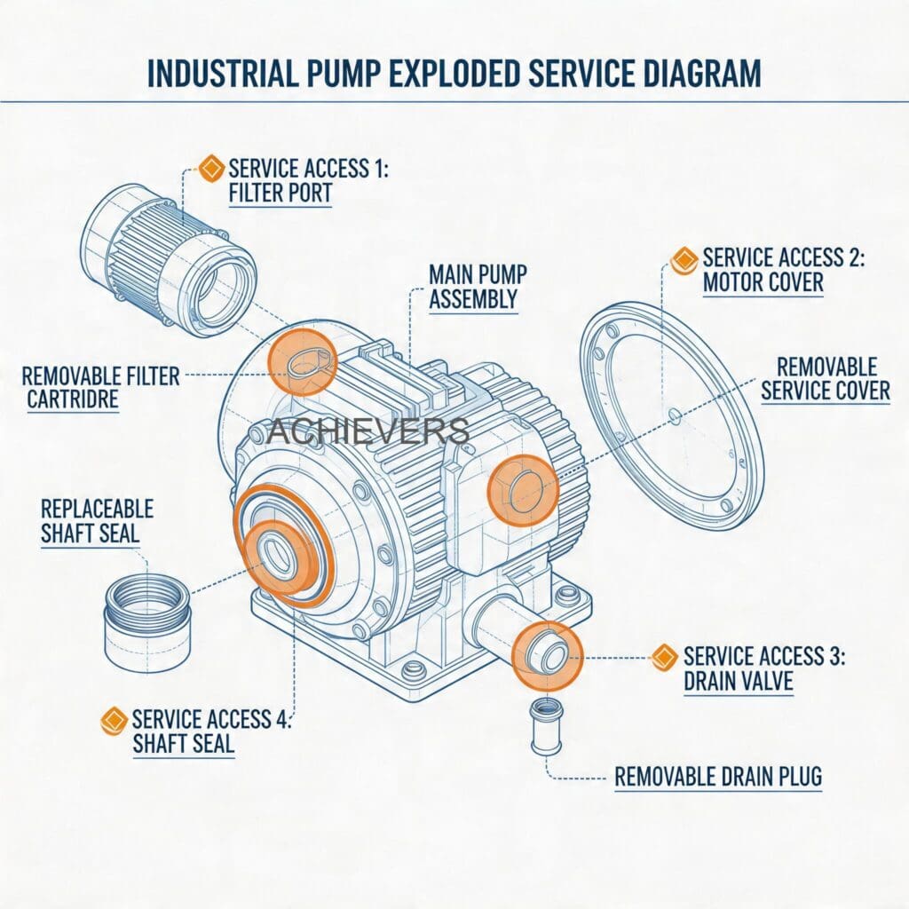
When implementing a global maintenance strategy, you must monitor the specific wear components. The oval gears, internal bearings, rotor shafts, and the integrated mesh strainer bear the brunt of the operational stress.
2. Preventive Maintenance Schedule
Implementing a strict, standardized maintenance schedule for your Oil Flow Meters ensures longevity and consistent accuracy across different viscosity ranges. Whether you are standardizing operations across continents or simply deploying an oil flow meter maintenance checklist in India, the Middle East, or the Americas, a universal, time-based and volume-based approach is essential.
Below is the recommended preventive maintenance matrix designed to align with ISO and API maintenance standards.
| Task | Frequency | Responsible | Est. Time | Notes |
| — | — | — | — | — |
| Visual External Inspection | Daily | Plant Operator | 5 mins | Check for casing leaks, register cap condensation, and flange integrity. |
| Differential Pressure Check | Weekly | Maintenance Tech | 10 mins | Monitor upstream/downstream pressure. High delta indicates filter blockage. |
| Integrated Strainer Cleaning | Monthly (or per 100k Liters) | Maintenance Tech | 20 mins | Remove and flush the integrated mesh strainer to prevent gear jamming. |
| Housing Seal Inspection | Quarterly | Mechanical Eng. | 30 mins | Check main body O-rings and gaskets for signs of chemical swelling or weeping. |
| Accuracy Verification (Field) | Quarterly | Instrumentation Tech | 45 mins | Run a known volume at standard operating flow to verify 0.02% repeatability. |
| Register & Terminal Check | Bi-Annually | Electrical Tech | 20 mins | Ensure terminal connections are tight; check for moisture in electronic variants. |
| Rotor/Oval Gear Inspection | Annually | Mechanical Eng. | 2 hours | Open measuring chamber. Inspect gears and shafts for scoring, pitting, or excessive wear. |
| Step-less Alignment Calibration | Annually | Metrology / QA | 1.5 hours | Formal recalibration utilizing the step-less alignment framework. |
| Bearing Replacement | Every 2-3 Years | Mechanical Eng. | 3 hours | Preventative replacement of rotor bearings before failure causes casing contact. |
| Full Overhaul | Every 5 Years | Authorized Service | 1 Day | Complete teardown, chemical bath cleaning, and full consumable replacement. |
3. Step-by-Step Procedures for Key Tasks
Routine maintenance should never be left to guesswork. Standard operating procedures (SOPs) protect both the equipment and the operator, particularly in ATEX-rated hazardous zones or high-pressure applications.
Procedure A: Integrated Mesh Strainer Cleaning Guide
The integrated mesh strainer protects the precision oval gears from welding slag, pipe scale, and fluid impurities. If ignored, the meter will suffer a high pressure drop and potential rotor seizure.
- Isolate the Meter: Close the upstream and downstream isolation valves to completely cut off fluid flow to the meter section.
- Depressurize the Line: Safely vent the pressure using the designated bleed valve into an approved catchment container, adhering to environmental regulations.
- Remove Strainer Cap: Using the appropriate metric wrench, loosen and remove the bolts securing the strainer housing cap.
- Extract the Mesh Basket: Carefully pull the integrated mesh strainer basket out of the housing, noting its orientation for reassembly.
- Chemical Cleaning: Submerge the mesh basket in a compatible, non-corrosive solvent bath to dissolve hardened mineral oil, vegetable oil, or heavy furnace oil residues.
- Air Purge: Use low-pressure compressed air (max 2 bar) to blow from the outside-in, clearing any lodged particulates from the mesh pores.
- Inspect the Cap O-ring: Check the strainer cap seal for flattening, cracks, or chemical degradation. Replace immediately if compromised.
- Reassembly and Priming: Reinstall the strainer, tighten bolts in a star pattern to ensure even seating, and slowly crack the upstream valve to prime the meter and purge trapped air.
Procedure B: Oil Flow Meters Calibration and Cleaning Guide (Measuring Chamber)
Over time, fluids like heavy heating oil or unrefined diesel can leave a film on the measuring elements, leading to a sluggish response or false readings.
- Lockout/Tagout (LOTO): Secure the fluid line and electrical systems (if using a digital output module) following your plant's safety protocols.
- Drain the Housing: Drain the residual oil from the measuring chamber entirely to prevent spills during disassembly.
- Remove the Front Cover: Unbolt the front casing carefully. Be prepared to catch any remaining fluid.
- Extract Oval Gears: Gently remove the oval gears from their respective shafts. Note the timing marks (often small punched dots) which must align during reassembly.
- Inspect the Chamber: Use a high-lumen flashlight to inspect the internal cavity and rotor shafts for scoring. Smooth surfaces ensure the low pressure drop required for gravity applications.
- Clean Components: Wash the gears and chamber interior with a compatible industrial solvent. Do not use abrasive brushes that could alter the volumetric clearances.
- Check Bearings: Spin the bearings manually. They should rotate freely without catching or grinding.
- Reassemble and Align: Reinstall the gears ensuring the timing marks perfectly align at a 90-degree offset. Replace the main body gasket, secure the cover, and verify operation at a low flow rate before returning to full duty.
4. On-Site Spare Parts to Stock
Supply chain delays shouldn't dictate your plant's uptime. Because these meters feature an inherently simple design built for quick and easy maintenance, stocking the right parts guarantees rapid serviceability. Industrial oil flow meters supplier guidelines suggest keeping the following spares on hand, especially for critical batching operations that interface with larger infrastructure like a Liquid Batching System.
| Part Description | Type / Criticality | Recommended Qty (per 5 meters) | When to Replace |
| — | — | — | — |
| Complete O-Ring / Gasket Kit | Consumable | 3 Kits | Every time the casing or strainer is opened; annually as preventive. |
| Integrated Mesh Strainer | Fast-Wear | 2 Units | If the mesh is torn, collapsed due to pressure, or permanently clogged. |
| Oval Gear Set | Critical Spare | 1 Set | If scoring exceeds 0.1mm, or if repeatability drops below the 0.02% threshold. |
| Rotor Bearings | High-Wear | 2 Sets | During the 2-3 year major inspection or if acoustic noise increases. |
| Register Cap / Glass | Hardware | 1 Unit | If cracked, clouded by chemical exposure, or compromised by impacts. |
5. Diagnosing Maintenance-Related Failures
Even with a robust preventive strategy, unexpected process variations can induce faults. Use this practical decision table to map failure symptoms back to specific maintenance oversights, allowing for rapid field diagnosis.
| Failure Symptom | Missed Maintenance Task | Corrective Action |
| — | — | — |
| Meter stops registering but fluid is flowing | Strainer bypassing / Particulate entry | Open chamber, remove debris jamming the oval gears. Check upstream filtration. |
| Gradual loss of accuracy (under-reading) | Chamber cleaning / Clearance check | Clean built-up residue on gears. If gears are worn from abrasives, replace them. |
| High differential pressure across meter | Strainer cleaning schedule missed | Isolate meter and thoroughly clean or replace the integrated mesh strainer. |
| Weeping fluid at the meter casing joints | Housing seal/O-ring inspection | Replace main cover O-rings and tighten flange bolts to specified torque settings. |
| Inconsistent batch totals or jumps | Gear timing / Bearing inspection | Inspect gears for chipped teeth or bearing failure causing irregular rotation. |
| Register display unreadable | Register cap weather sealing | Replace register cap, ensure 90º orientation is seated flat, replace desiccant if used. |
Common Mistake to Avoid
Air Entrainment Ignorance: A volumetric oval gear meter will measure everything that passes through it—including air. A common mistake operations managers make is blaming the meter for accuracy drift when the actual culprit is an empty upstream supply tank pulling air into the line. Always ensure air eliminators are installed and maintained upstream of your oil flow meters, especially in pump-driven offloading applications, to prevent false volumetric inflation.
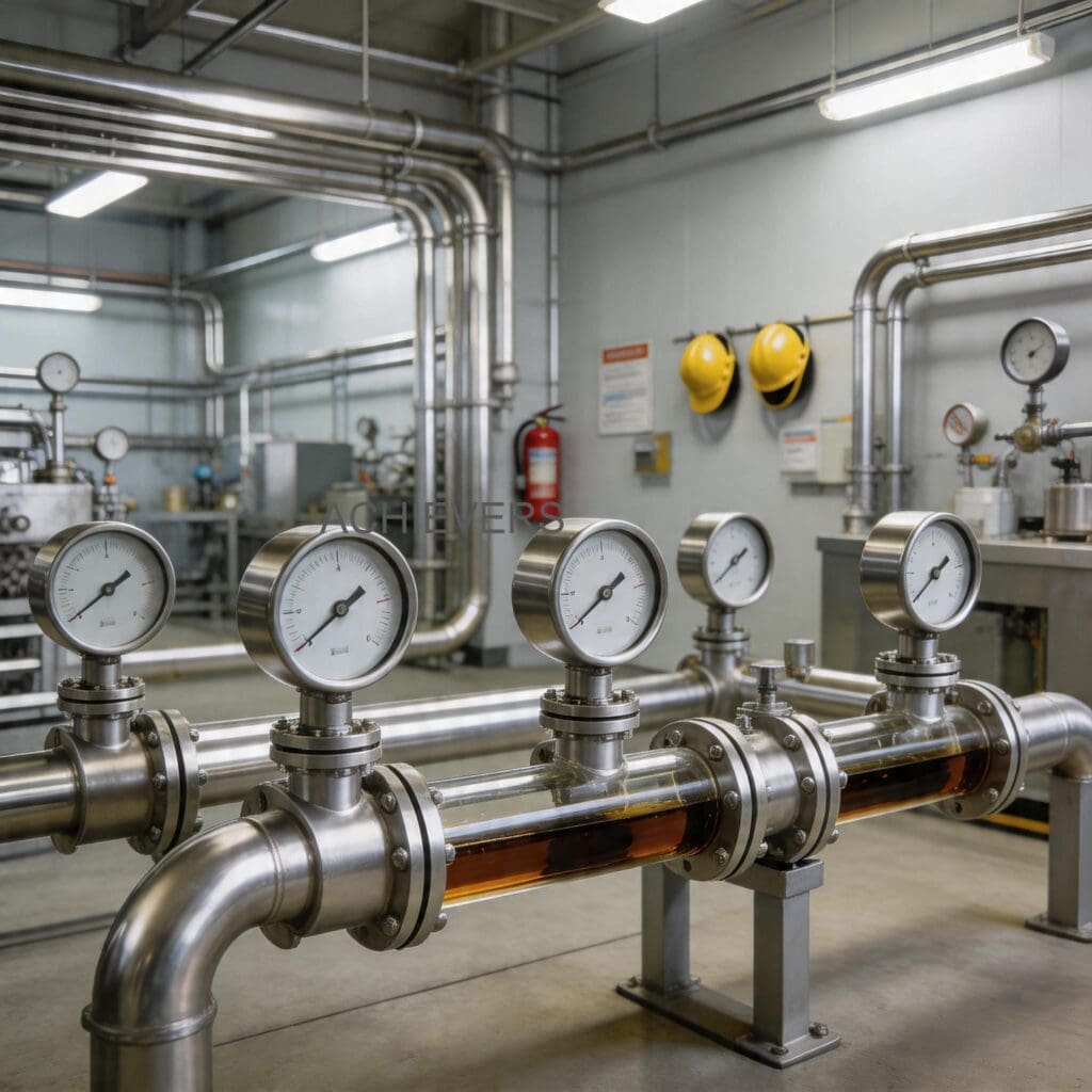
6. Extending Service Life in Harsh Global Conditions
Industrial fluid transfer rarely happens in perfect, laboratory-like environments. Whether dealing with heavy furnace oil in sub-zero winter temperatures or lubricating fluids in aggressive, high-humidity coastal zones, your meters must be protected against external extremes. Adapting to these conditions aligns with stringent CE and API standards for equipment longevity.
Managing Viscosity and Temperature Extremes
Oil flow meters handle a massive range of fluids—from highly viscous mineral oils to thin vegetable cooking oils. In low-temperature environments, high-viscosity fluids can exert immense mechanical stress on the rotor shafts upon startup. Always ensure heat tracing and insulation jackets are functioning properly around the piping and meter housing. Implement a soft-start procedure for your pumps to gradually introduce flow, preventing pressure spikes from slamming cold, thick oil into stationary oval gears.
Controlling Corrosive and Hazardous Environments
For operations in corrosive coastal environments or offshore platforms, the exterior of the meter is just as vulnerable as the interior. Standardize the application of heavy-duty, marine-grade protective coatings on the external casing. If the meter is integrated with electrical pulse outputs, ensure all junction boxes are strictly maintained to ATEX or UL hazardous area standards. Treat threaded connections with anti-seize compounds during every maintenance window to prevent galvanic corrosion from locking the housing bolts.
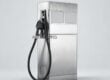
Integration with Larger Fuel Systems
When these flow meters are utilized in large-scale vehicle refueling or combined with equipment like a Fuel Flow Meter, flow harmonization is critical. Ensure that upstream pumps are sized correctly so the meter operates within the middle 60% of its rated flow capacity. Running a meter constantly at its absolute maximum flow rate accelerates bearing wear exponentially, while running it too slowly can allow high-viscosity fluid to slip past the gears, skewing the 0.02% repeatability.
FAQ
Q: How often should I perform an oil flow meters accuracy verification procedure?
A: For high-value custody transfer or precise petrochemical blending, accuracy should be verified quarterly using a master meter or a calibrated proving tank. For general lubrication or furnace oil transfer, an annual verification and step-less alignment calibration is typically sufficient.
Q: Can I use water to flush the meter during cleaning?
A: No. Introducing water into a meter designed for oils (especially hydraulic or mineral oil) can cause flash rusting on carbon steel components and alter the fluid dynamics. Always use a compatible, approved petroleum-based solvent for flushing.
Q: Why does my meter register flow when the downstream valve is closed?
A: This usually indicates hydraulic shock, thermal expansion of the fluid in the line, or air pockets compressing and expanding. Ensure proper check valves and thermal relief valves are installed in the piping system.
Q: What is the maximum pressure drop I should accept before cleaning the strainer?
A: While it varies by fluid viscosity and line size, a general rule is to service the integrated mesh strainer if the differential pressure exceeds 0.5 bar (7.5 psi) above the baseline clean-filter pressure.
Q: Will changes in oil viscosity affect the meter's accuracy?
A: Oval gear positive displacement meters are highly immune to viscosity changes. Because they measure discrete volumetric pockets, their accuracy remains consistent whether you are pumping thin heating oil or thick, cold furnace oil, provided the flow rate remains within specification.
Q: Are the internal gears interchangeable between different meters?
A: No. Oval gears are precision-machined and matched as pairs to achieve the repeatability of better than 0.02%. If one gear is damaged, the entire set must be replaced together.
Q: How do I handle maintenance if the meter is installed vertically?
A: The meters are not affected by outside components caused by the establishment and can function in vertical lines. However, during maintenance, ensure the line is fully drained. You may also need to support the heavy casing cover before removing the flange bolts to prevent the gears from falling out.
To ensure your fluid transfer infrastructure operates at peak efficiency without measurement losses, standardizing your equipment is the crucial first step. If you need assistance selecting the correct volumetric metering technology, upgrading your current lines, or identifying the right replacement components, contact our engineering team today with your required flow rate, fluid application, and site operating conditions.