In Indian industrial operations—whether mining, construction, or manufacturing—diesel is essentially liquid gold. With high-speed diesel prices hovering around ₹90 to ₹100 per liter, even a 1% measurement error in your fuel transfer system can result in lakhs of rupees lost over a single financial year. When plant managers and industrial engineers face inaccurate readings, erratic flow data, or ticket printing failures, the immediate reaction is often to assume the meter is permanently broken. This leads to costly downtime, halted genset operations, and unnecessary equipment replacement.
However, replacing an expensive piece of equipment before diagnosing the root cause is a costly error. More often than not, Diesel Flow Meter troubleshooting comes down to isolating external factors: air ingress from poor plumbing, sensor fouling from contaminated Indian fuel, voltage fluctuations impacting the electronics, or simple calibration drift. By taking a systematic, engineering-led approach to diagnosis, your maintenance team can pinpoint the exact failure mode and restore accurate measurement without replacing the entire unit.
This guide provides a step-by-step diagnostic framework for operations managers to quickly resolve inaccurate readings, flow fluctuations, and ticket printing issues, minimizing diesel shrinkage and keeping operations running smoothly.
1. Quick Reference: How Diesel Flow Meter Works
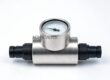
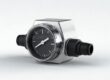
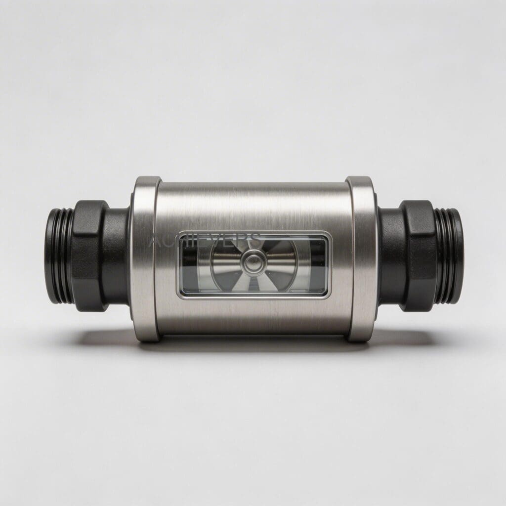
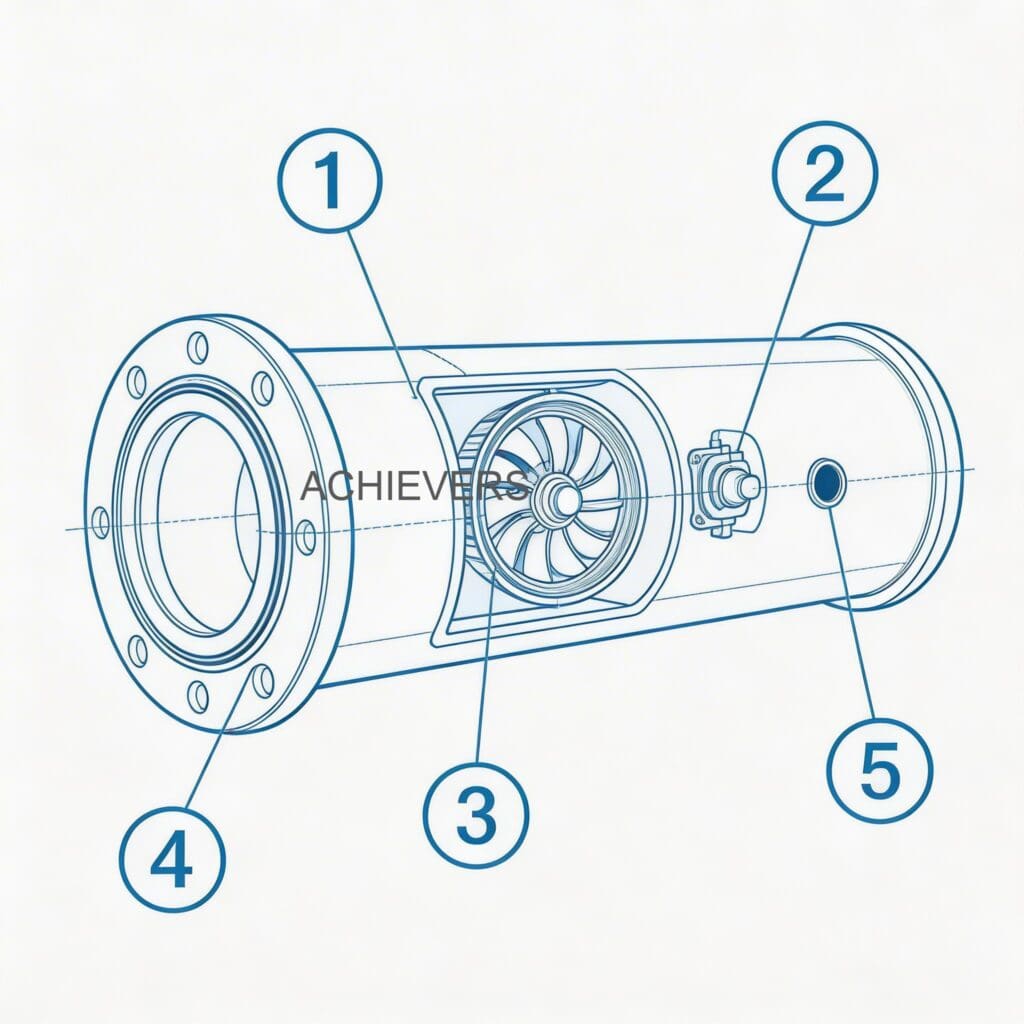
Before dismantling your fuel lines, it is critical to understand the operating principle of the Diesel Flow Meter. The Achievers Make meters utilize a time-tested oscillating piston design. Fluid entering the meter chamber causes the piston to oscillate in a highly predictable, circular motion. Because the piston is the single moving component within the assembly, mechanical wear is minimized, ensuring reliable operation over millions of liters.
As the piston oscillates, a solid-state magnetic sensor detects each rotation. This ultra-low-powered electronic sensor translates the mechanical movement into high-resolution electronic pulses (an NPN output signal). These pulses are then processed by the digital display head to show instantaneous flow rate and totalized volume. When equipped, the system sends this exact batch data to a ticket printer for undeniable proof of transaction.
Quick ROI Snapshot
Typical payback period for diagnosing and fixing a 2% calibration error: 2 to 3 weeks (based on a 5,000 L/day fuel transfer rate).
Cost of ignoring air ingress: Up to ₹3,00,000 annually in over-billed fuel deliveries due to metering "air" instead of liquid.
Below are the baseline technical specifications of the unit. Comparing your site's operating conditions against these factory parameters is the first step in diesel flow meter calibration issue diagnosis.
| Specification Parameter | Factory Standard Rating | Relevance to Troubleshooting |
| — | — | — |
| Flow Range | 1.0 LPH to 24,000 LPH | Operating below or above this range causes massive accuracy drift or internal damage. |
| Accuracy & Repeatability | +/- 0.2% Accuracy; +/- 0.1% Repeatability | A meter failing to repeat its error margin usually indicates mechanical wear or air ingress, not just calibration drift. |
| Viscosity Range | 0.612 to 5.35 mm2/s | Heavy sludge or highly degraded diesel can exceed limits, causing rotor drag. |
| Max Operating Pressure | 10 MPa (approx. 100 Bar) | Surpassing this via water hammer can rupture O-rings and cause internal bypassing. |
| Ambient & Fluid Temp | -40 to 80 C (up to 150 C for specialized builds) | Excessive heat from direct Indian summer sun can overheat standard electronic enclosures. |
| Power Supply | 5 – 24V DC | Voltage drops from unstable site power can cause erratic display behavior or sensor failure. |
2. Troubleshooting Matrix
When a metering system fails in the field, symptoms often overlap. A blank display could be a dead battery, a blown fuse, or water ingress from a recent monsoon downpour. Use this comprehensive troubleshooting matrix to match your specific symptom to the likely engineering cause, saving hours of blind testing.
| Symptom | Likely Cause | Diagnosis Steps | Fix |
| — | — | — | — |
| Zero reading on display (but flow is present) | Sensor failure, severed cable, or jammed internal piston. | Check NPN output with a multimeter. Isolate flow and check if piston moves freely. | Clean internal chamber. Replace magnetic sensor if dead. |
| Erratic / fluctuating flow readings | Electrical noise (EMI), air in the line, or loose terminal connections. | Inspect cable routing near VFDs/heavy motors. Check suction lines for air leaks. | Reroute cables in shielded conduits. Fix suction line leaks and install an air eliminator. |
| Inaccurate reading (Over-registering) | Measuring air alongside diesel. This is the classic "diesel flow meter air in line symptoms". | Inspect upstream pipe joints, pump seals, and ensure the tank is not running dry. | Install upstream air eliminator. Tighten all suction-side flanges and replace worn pump seals. |
| Inaccurate reading (Under-registering) | Worn oscillating piston allowing fluid bypass, or heavy debris in chamber. | Conduct bucket test. Open meter chamber and inspect piston and O-rings for scoring/wear. | Replace internal piston/rotor. Clean strainers to prevent future scoring. |
| Display is completely blank | Power supply failure, loose internal ribbon cable, or blown protective fuse. | Check input voltage (5-24V DC). Open weatherproof enclosure and inspect connections. | Restore stable DC power. Re-seat ribbon cables. Replace fuse if applicable. |
| High pressure drop / severely restricted flow | Clogged internal wire mesh filter or frozen oscillating piston. | Monitor upstream/downstream pressure gauges. Remove and inspect the built-in strainer. | Wash the reusable wire mesh filter in clean solvent. Reinstall and test flow. |
| Output signal loss (to PLC or external batch controller) | Failed NPN solid-state sensor or voltage drop across long cable runs. | Measure voltage at the PLC input. Test continuity of the signal cable. | Replace signal cable with thicker gauge or install a signal amplifier. Replace sensor if no pulses. |
| Fluid leakage from meter body | Ruptured NBR/Viton O-ring due to pressure spike or chemical degradation. | Clean meter exterior, pressurize the line, and visually inspect flange and cover joints. | Replace O-rings with correct material (Viton for harsh chemicals/biodiesel blends). |
| Ticket printer prints blank paper | Thermal paper roll is installed backward. | Open printer housing and check paper orientation. Thermal paper only prints on one side. | Flip the thermal paper roll. Run a test print batch. |
| Ticket printer output is garbled/unreadable | Baud rate mismatch, low voltage, or loose communication cable. | Check RS232/RS485 comms settings in meter and printer. Check power supply to printer. | Match baud rates. Secure all wiring terminals. Ensure dedicated power supply. |
3. Step-by-Step Field Diagnosis Procedure
When your operators report that the Diesel Flow Meter is giving faulty numbers, do not immediately attempt to recalibrate the software. Recalibrating a meter to compensate for a mechanical issue (like a torn O-ring or clogged filter) will only temporarily hide the problem and lead to worse errors later.
Follow this 8-step field diagnosis procedure using basic tools (multimeter, clean buckets, standard wrenches, and a Legal Metrology approved volumetric measure).
Step 1: Verify Power Quality and Grounding
Industrial sites in India frequently suffer from severe voltage fluctuations. Use your multimeter to verify that the meter is receiving a stable 5 to 24V DC. Check the grounding. Improper earthing can cause static buildup from the flowing diesel, which interferes with the NPN magnetic sensor and causes erratic pulse counting.
Step 2: Inspect for Air Ingress on the Suction Side
Air is the enemy of volumetric measurement. If your meter is over-registering, it is almost certainly counting air bubbles. Check all pipe joints, valves, and pump seals situated before the meter. Ensure the fuel tank level isn't dropping below the suction pipe inlet, creating a vortex.
Step 3: Clean the Built-in Wire Mesh Filter
Achievers flow meters feature a high-capacity reusable wire mesh filter. Isolate the meter using upstream and downstream isolation valves. Depressurize the line safely. Remove the filter housing, extract the mesh, and wash it thoroughly in clean solvent. A clogged filter starves the meter, causing cavitation and false readings.
Step 4: Conduct a Proving / Bucket Test
To diagnose diesel flow meter inaccurate reading causes and fixes, perform a volumetric test. Dispense exactly 20 liters into a certified Legal Metrology proving measure. Compare the physical volume against the digital display.
- If the error is consistent (e.g., always 2% low), it is a calibration drift.
- If the error fluctuates wildly (2% low, then 5% high), you have a mechanical issue or air in the line.
Step 5: Inspect the Magnetic Sensor and Wiring
If the flow rate fluctuates wildly or drops to zero while fuel is visibly flowing, the NPN solid-state sensor may be loose or fouled. Open the flameproof/weatherproof enclosure. Ensure all terminal screws are tight. Look for corrosion on the pins—a common issue during high-humidity monsoons.
Step 6: Diagnose Ticket Printer Comms
If dealing with a diesel flow meter with ticket printer not printing, first verify the basics: is there paper, and is it inserted correctly (thermal side up)? If the paper is correct but it refuses to print, check the data cable between the meter head and the printer. Use your multimeter to check for continuity. Ensure the printer has its own stable 12V or 24V power source, as voltage drops during pump startup can cause the printer to reset mid-batch.
Step 7: Dismantle and Inspect the Oscillating Piston
If flow is restricted and the filter is clean, the oscillating piston may be jammed by hard particulates (like rust from old mild-steel diesel tanks). Carefully unbolt the front cover. Remove the piston and inspect the chamber walls. If you see deep vertical scoring, the fluid has bypassed the meter. The chamber and piston must be cleaned with a fine emery cloth, or replaced if damage is severe.
Step 8: Reassemble, Bleed the Line, and Recalibrate
Reassemble the unit using fresh NBR or Viton O-rings. Never reuse flattened O-rings. Slowly open the upstream valve to allow fuel to enter the chamber, utilizing a bleed valve to vent trapped air. Once all air is purged and only solid liquid flows, conduct a final bucket test and adjust the electronic calibration factor (K-factor) if necessary.
4. Installation and Setup Errors That Cause Ongoing Problems
A perfectly manufactured flow meter will fail repeatedly if the mechanical installation is flawed. Many recurring complaints about a [Diesel Flow Meter] acting erratically trace back to the day it was commissioned.
Common Mistake to Avoid
Using standard white Teflon tape on upstream pipe threads is a major hazard for oscillating piston meters. When fittings are tightened, tiny shreds of Teflon tape break off, travel downstream, and wrap around the internal piston, jamming the meter completely. Always use liquid thread sealant (like Loctite) suitable for hydrocarbons on pre-meter pipework.
If you are experiencing constant failures, check your site against this installation error table:
| Installation Error | Symptom / Consequence | Correction / Best Practice |
| — | — | — |
| Installed on the suction side of the pump | Meter runs under negative pressure, causing dissolved air in diesel to break out (cavitation), leading to massive over-registering. | Always install the flow meter on the discharge (pressure) side of the pump. |
| No upstream air eliminator | Pipeline air from empty tanks or loose joints passes through the meter, billing you for air. | Install an automatic air eliminator and strainer assembly immediately upstream of the meter. |
| Signal cables run alongside heavy power lines | High voltage lines to motors/VFDs induce electromagnetic interference (EMI), causing false pulses on the display. | Route NPN signal cables in dedicated, grounded metal conduits separated from power lines. |
| Piping stress on meter flanges | Misaligned pipes forced into position stretch the meter body, causing internal binding of the piston. | Support heavy pipes with independent brackets. Flanges should align naturally before bolting. |
| Inadequate filtration | Indian diesel often contains dust and silica. Skipping the 100-micron strainer allows debris to score the measuring chamber. | Ensure a Y-strainer or basket strainer is installed upstream, alongside the meter's internal mesh. |
| Incorrect display orientation | Operators cannot easily read the digital display, leading to manual logging errors. | Rotate the electronic display head (usually adjustable in 90-degree increments) for eye-level visibility. |
5. Preventive Maintenance to Avoid Recurrence
Industrial environments in India are punishing. Summer temperatures inside a metal enclosure can exceed 60 °C, while monsoon humidity introduces moisture that degrades electronics. Setting up a strict preventive maintenance schedule is the only way to ensure your diesel flow meter for industrial fuel transfer in India delivers a decade of accurate service.
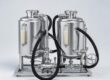
If your facility also utilizes automated batching, cross-applying these maintenance principles to your Liquid Batching System will dramatically reduce overall plant downtime.
Daily Checks:
- Visually inspect the meter body and flanges for weeping fuel.
- Verify the digital display is clear and not showing any low-battery or fault codes.
- Ensure the ticket printer has an adequate paper roll for the shift.
Weekly Checks:
- Perform a quick 10-liter or 20-liter bucket test against a known calibration measure to catch any early signs of calibration drift.
- Check the differential pressure across your upstream strainers.
Monthly Checks:
- Isolate the line and clean the internal wire mesh filter. In particularly dusty environments (like mining or cement plants), this may need to be a weekly task.
- Open the ticket printer housing and blow out paper dust with compressed air to prevent paper jams.
- Inspect the weatherproof enclosure seals. If the rubber gasket is cracking, replace it before monsoon season hits to protect the PCB.
Annual Checks:
- Schedule a formal calibration and certification as per the Legal Metrology Act requirements.
- Replace internal O-rings (NBR or Viton) preventatively.
- Check earthing pit resistance to ensure static electricity from fuel transfer is safely dissipating.
6. When to Call Service vs. Fix Yourself
Knowing your team's limitations is crucial. While the oscillating piston design is inherently simple to maintain, certain failures require factory-level intervention.
Fix it Yourself:
- Cleaning strainers and Y-filters.
- Replacing torn flange gaskets and O-rings.
- Fixing basic wiring, replacing a blown fuse, or restoring stable 24V DC power.
- Clearing thermal paper jams and replacing printer cables.
- Conducting routine volumetric bucket tests and adjusting the K-factor software calibration.
Call Achievers Service / Your Diesel Flow Meter Supplier:
- Deep Chamber Scoring: If the internal aluminum or stainless steel chamber has deep gouges from pumping rocks or welding slag, the meter cannot be calibrated. It requires factory remachining or replacement.
- Lightning Strikes / Severe Electrical Surges: If the entire PCB is scorched and unresponsive, the electronic head must be replaced and reprogrammed.
- PESO / Legal Metrology Sealing: If the meter is used for custody transfer or commercial billing and the legal metrology lead seal needs to be broken for internal repairs, you must coordinate with certified personnel to re-seal the unit post-repair to remain compliant with Indian regulations.
- Persistent Unexplainable Drift: If you have ruled out air ingress, cleaned the filters, and the meter still drifts by 3-5% every few days, the internal rotor may be warped from extreme high temperatures and requires factory diagnostics.
FAQ
Q: Why is my diesel flow meter reading a higher volume than the actual fuel transferred?
A: This is almost always caused by air passing through the meter. The meter cannot distinguish between a liter of liquid diesel and a liter of air. Check your pump suction lines for leaks and ensure an air eliminator is installed.
Q: How often should I calibrate my industrial diesel flow meter in India?
A: For internal accounting, a check every 3 to 6 months is recommended due to harsh site conditions. If the meter is used for custody transfer or commercial sales, it must be verified and stamped annually per the Legal Metrology Act.
Q: Can I use this same flow meter for Biodiesel blends?
A: Yes, but you must ensure the internal elastomers are compatible. Standard NBR O-rings may degrade with high-concentration biodiesel. Ensure your unit is fitted with Viton O-rings, which are highly resistant to biofuels and aggressive solvents.
Q: The ticket printer turns on and feeds paper, but the paper is completely blank. Why?
A: Thermal printers do not use ink. They use heat-sensitive paper that only reacts on one side. You have likely loaded the thermal paper roll upside down. Flip the roll over and print a test ticket.
Q: Does the Achievers oscillating piston flow meter require straight pipe runs before and after?
A: Unlike turbine or ultrasonic flow meters, positive displacement meters (like oscillating piston types) do not require straight upstream or downstream pipe runs. They measure discrete volumes of fluid, making them ideal for tight installation spaces in mobile bowsers or compact skids.
Q: How do monsoon humidity and heavy rains affect the electronics?
A: Moisture can cause corrosion on the NPN sensor terminals and PCB. Always ensure the weatherproof or flameproof enclosures are tightly bolted down with intact rubber gaskets. Use silica gel packets inside the enclosure if your site experiences extreme humidity.
Q: Can this meter handle high-temperature heavy fuel oil (HFO) for power generation?
A: The standard diesel meter is rated up to 80 °C. However, Achievers manufactures specialized high-temperature variants capable of handling hot FO, HFO, and LSHS up to 150 °C. You must specify this requirement during procurement.
If your facility is struggling with persistent fuel measurement errors, don't let inaccurate data drain your operational budget. Reach out to the technical team at Achievers Pumps and Valves to properly diagnose your system. Contact us today with your specific flow rate requirements, fluid type, and site conditions, and our engineers will help you select, troubleshoot, or upgrade to the most reliable metering solution for your specific application.