Unaccounted fuel loss is one of the most persistent drains on operating margins for industrial facilities, fleet depots, and power generation plants. When an operation relies on precise fluid handling, even a 1% measurement error on a high-volume fuel line can result in thousands of liters of unrecorded diesel or gasoline over a single fiscal quarter. If you are an operations manager or plant engineer, recognizing the early signs of meter drift, erratic pulsing, or pressure drops is critical to maintaining profitability and process control.
Effective Fuel Flow Meter troubleshooting requires moving beyond guesswork. It demands a systematic approach to fluid dynamics, mechanical inspection, and electronic verification. Whether you are dealing with inaccurate readings caused by air entrapment, unexplained pressure drops disrupting your pump heads, or a totalizer that has simply stopped registering, rapid and accurate diagnosis is your first line of defense against costly downtime.
This comprehensive industrial fuel flow meter diagnosis guide will walk you through the structural mechanics of your metering equipment, provide a robust troubleshooting matrix, and outline the exact field procedures needed to restore ±1% accuracy to your fluid transfer systems.
Quick ROI Snapshot:
Proactive meter troubleshooting and calibration can prevent a 2% volumetric drift on a 100 L/Min transfer line. For a facility operating just 4 hours a day, correcting this drift saves approximately 480 liters of unmetered fuel per day. Typical payback period for dedicating maintenance hours to meter diagnostics: Under 14 days.
1. Quick Reference: How Your Fuel Flow Meter Works
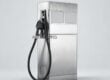
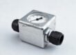
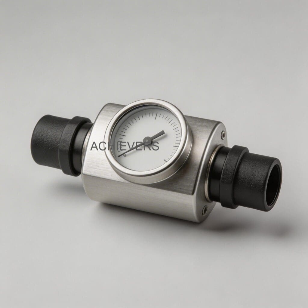
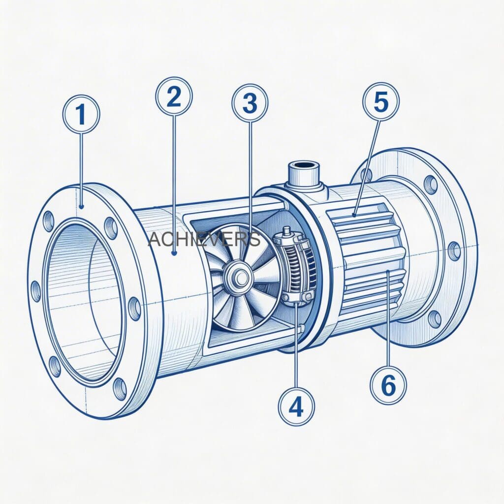
Before diving into fault isolation, it is essential to understand the functional baseline of your equipment. Most high-accuracy industrial fuel meters, including the Achievers CE-104 series, are positive displacement (PD) meters.
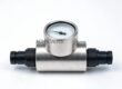
A positive displacement meter measures fluid by trapping a fixed volume of liquid within a precise mechanical chamber and passing it downstream. The measurement part of the Fuel Flow Meter consists of two closely toleranced curved gears (often oval gears) that mesh together within a sealed shell. As fluid pressure forces the gears to rotate, a known volume of diesel, kerosene, or gasoline is displaced with every revolution. This mechanical rotation is then magnetically or mechanically transferred to a vacuum-sealed, dry totalizer.
Because the system relies on physical displacement, it is highly sensitive to low flow rates and remains exceptionally accurate across its entire flow range, provided the fluid is clean and free of compressible gases.
Baseline Technical Specifications:
| Specification | Technical Detail |
| — | — |
| Model Number | CE-104 |
| Supported Mediums | Diesel, Kerosene, Gasoline |
| Inlet Connection Size | BSPT / NPT 1” |
| Optimal Flow Rate Range | 6 – 100 L/Min (Rated up to 120 L/Min) |
| Metric Accuracy | ±1% within the optimal flow range |
| Totalizer Display | Digital, Accumulative Counting Digit: 8 Digits |
| Internal Mechanics | Positive Displacement, Self-lubricating curved gears |
| Environmental Protection | Vacuum sealed, leak-proof, dry totalizer |
2. Troubleshooting Matrix: Fuel Flow Meter Inaccurate Readings Causes and Fixes
When a Fuel Flow Meter strays from its ±1% baseline, the root cause typically falls into one of three categories: mechanical binding, fluid condition anomalies (like air entrapment), or electronic/display faults. Use this diagnostic matrix to trace symptoms to their source.
| Symptom | Likely Cause | Diagnosis Steps | Fix |
| — | — | — | — |
| Zero Reading / Totalizer Not Registering | Broken gear coupling or totalizer failure | Check if fluid is flowing downstream. If yes, inspect the magnetic coupling or digital display battery/wiring. | Replace the internal coupling or display module. Restore power if digital type. |
| Over-reading (Meter registers more than actual volume) | Air entrapment in the fluid line | Inspect suction side of the pump for leaks. Look for vortexing in the supply tank. | Install an air eliminator upstream of the meter. Tighten suction line fittings. |
| Under-reading (Meter registers less than actual volume) | Internal wear causing "slip" or fluid bypassing gears | Measure actual output into a calibrated volumetric prover. Check for abrasive wear on curved gears. | Replace worn gears. Recalibrate meter to account for minor clearance increases. |
| Erratic or Pulsing Display Readings | Severe pressure fluctuations or pump cavitation | Monitor upstream pressure gauges. Listen for rattling in the pump (cavitation). | Install a pressure regulating valve. Clean suction strainers to prevent pump starvation. |
| Sudden Pressure Drop Across Meter | Clogged upstream strainer or jammed gears | Check differential pressure across the meter. Isolate and inspect the internal measuring room. | Clean the upstream 60-mesh strainer. Remove debris from the measuring chamber. |
| Excessive Mechanical Noise | Lack of lubrication or foreign debris in gears | Verify if the correct fluid is being pumped (do not pump dry or use for acids). Isolate and open casing. | Flush chamber with clean solvent. Ensure fluid provides adequate lubricity (e.g., diesel). |
| Gradual Accuracy Drift Over Months | Particulate buildup or minor internal wear | Perform a fuel flow meter calibration check against a master meter or prover tank. | Adjust calibration factor on the digital totalizer. Schedule routine gear inspection. |
| External Leakage Around Housing | O-ring failure or housing bolt fatigue | Wipe down meter housing. Pressurize system to deadhead and visually inspect seals. | Replace housing O-rings. Torque flange bolts to manufacturer specifications. |
| Output Signal Loss (to batch controller) | Damaged pulse transmitter or loose wiring | Use a multimeter to check for continuity and pulse generation at the meter terminals. | Resecure terminal connections. Replace faulty pulse encoder/sensor. |
| Valve Not Responding / Flow Blocked | Downstream blockage or total gear lockup | Attempt to manually rotate gears (if accessible). Check downstream dispensing nozzles. | Clear downstream blockage. If gears are locked, rebuild measuring chamber internals. |
3. Step-by-Step Field Diagnosis Procedure
When operations are halted due to fluid handling failures, maintenance teams need a structured diagnostic path. Jumping straight to dismantling the meter often introduces dirt into the precision measuring room and voids warranties. Follow this checklist for safe, effective field troubleshooting.
Required Tools: Calibrated proving can (e.g., 20L or 50L), multimeter, differential pressure gauge, adjustable wrenches, clean shop rags, and appropriate replacement O-rings.
- Verify the Operating Conditions: Ensure the fluid being transferred matches the meter's rating (Diesel, Kerosene, Gasoline). These meters are strictly forbidden for measuring corrosive acids or highly viscous heavy fuel oils beyond their design limits.
- Safety and Isolation: Implement Lockout/Tagout (LOTO) on the pump system. Close the upstream and downstream isolation valves to completely isolate the meter from line pressure.
- Inspect the Upstream Strainer: Before touching the meter, remove the housing of the upstream strainer. A clogged strainer is the number one cause of extreme pressure drops and pump cavitation. Clean the mesh and reinstall.
- Check for Air Entrapment Dynamics: If the meter was over-reading, inspect the suction side of the system. Ensure the supply tank fluid level is high enough to prevent vortexing. Verify that the air eliminator (if installed) is functioning and venting properly.
- Differential Pressure Test: Re-energize the system safely. Install pressure gauges immediately upstream and downstream of the meter. A pressure drop (head loss) significantly higher than the manufacturer's curve indicates mechanical binding inside the meter.
- Internal Gear Inspection: Isolate the system again. Carefully remove the meter's faceplate. Inspect the self-lubricating curved gears. They should rotate freely by hand. Look for scoring, metal shavings, or lodged debris.
- Electronic/Totalizer Check: For digital meters, check the battery voltage or external power supply. If the display is blank or characters are fading, replace the power source. Verify the wire harness connecting the sensor to the totalizer.
- Volumetric Calibration Run: Dispense fuel into a certified volumetric proving can at a steady flow rate (e.g., 50 L/Min). Compare the actual liquid volume in the prover to the meter's digital reading. Calculate the percentage error.
- Recalibration Adjustment: If the physical condition is perfect but the meter drifts by 2-3%, access the digital calibration menu. Adjust the internal K-factor (pulse-per-liter ratio) to bring the meter back to absolute ±1% precision.
Common Mistake to Avoid:
Bypassing the Strainer. Many facilities remove clogged upstream strainers to temporarily "fix" a flow rate issue. Doing this allows welding slag, rust scale, and pipe tape directly into the meter. Because positive displacement meters have micro-millimeter clearances between the curved gears and the shell, passing solid debris will instantly score the chamber, causing irreversible accuracy loss (slip) and requiring a complete unit replacement.
4. Installation and Setup Errors That Cause Ongoing Problems
Even the most robust Diesel Flow Meter will fail if the initial installation violates fluid dynamic principles. If your meter requires constant troubleshooting, check this table to see if a fundamental setup error is to blame.
| Installation Error | Resulting Symptom | Necessary Correction |
| — | — | — |
| Lack of Air Eliminator | Meter spins faster than actual liquid flow (air is measured as volume). | Install a mechanical air eliminator directly upstream of the meter. |
| No Upstream Filtration | Sudden gear lockups, frequent pressure drops, scored internal housing. | Install a Y-strainer or basket strainer (minimum 60-mesh) before the meter inlet. |
| Severe Pipe Strain | External leakage, binding gears due to warped outer casing. | Support piping with brackets. Do not use the meter to pull misaligned pipes together. |
| Operating Below Minimum Flow | Under-reading. Fluid slips past gears without registering. | Size the meter correctly. For a 1" inlet, maintain flow above the 6 L/Min threshold. |
| Incorrect Orientation | Entrapped air pockets inside the measuring chamber, erratic pulses. | Install strictly according to manufacturer flow-arrow directions. Keep gear shafts horizontal. |
| Excessive Flow Velocity | Premature gear wear, high head loss, noisy operation. | Ensure pump output does not exceed the maximum rated 100-120 L/Min. |
5. Preventive Maintenance to Avoid Recurrence
Troubleshooting is reactive; maintenance is proactive. Because the CE-104 series features self-lubricating gears and a dry totalizer, mechanical upkeep is minimal, but fluid conditioning is paramount.
To ensure a long, maintenance-free working life, establish a monthly and quarterly maintenance protocol. Monthly, inspect all flange connections (BSPT/NPT 1" threads) for micro-leaks. A slight weep on the suction side will pull air into the line, throwing off your volumetric totals. Quarterly, remove and ultrasonically clean the upstream strainers.
Bi-annually, perform a documented calibration check. Fluid characteristics can change slightly with extreme seasonal temperature fluctuations. Performing a quick flow-test into a prover can allows you to tweak the digital calibration factor, ensuring your fuel consumption tracking remains financially accurate.
6. When to Call Service vs. Fix Yourself
Knowing the limits of in-house repair saves time and prevents accidental voiding of equipment warranties.
What you should fix yourself:
- Cleaning blocked strainers and replacing dirty fuel filters.
- Correcting suction-side leaks causing air entrapment.
- Replacing digital display batteries or reconnecting loose sensor wiring.
- Performing standard volumetric proving and digital K-factor recalibration.
When you need fuel flow meter supplier support:
- The meter's internal shell is deeply scored and requires factory re-machining or complete replacement.
- The curved gears are chipped or heavily worn and you do not have exact OEM replacement parts.
- The meter is used in an ATEX-rated hazardous environment and the electrical seal has been breached.
- You require officially certified calibration documentation for regulatory or custody-transfer compliance.
If you are dealing with large-scale fuel tracking across a fleet, consider consulting with experts about integrating a comprehensive Fuel Consumption Meter system, which can automate much of the diagnostic and reporting processes.
FAQ
Q: Why does my fuel flow meter read higher than the actual volume dispensed?
A: This is almost always caused by air entrapment in the fluid line. Positive displacement meters measure volume, and compressible air moving through the gears will register as liquid fuel. Inspect your suction lines for leaks and install an air eliminator.
Q: How often should I calibrate my industrial fuel flow meter?
A: For internal process control, a bi-annual calibration check is recommended. However, if the meter handles highly variable temperatures or dirty fuels, quarterly checks using a certified proving can will ensure you maintain the ±1% accuracy rating.
Q: Can I use this fuel meter for water or highly corrosive chemicals?
A: No. Meters designed for petroleum-type liquids (diesel, kerosene, gasoline) rely on the fluid itself to lubricate the internal curved gears. Measuring water or prohibited corrosive acids will cause immediate mechanical binding and permanent internal damage.
Q: What causes a sudden, massive pressure drop across the meter?
A: The most common cause is a severely clogged upstream strainer. If the strainer is clean, check for foreign debris that may have bypassed the filter and lodged between the curved gears and the measuring chamber shell.
Q: The digital display is fading or erratic. Do I need a whole new meter?
A: Usually, no. Fading displays or erratic digital output on a dry totalizer generally point to a depleted battery, a loose internal wiring connection, or moisture ingress in the display head. The electronic module can often be replaced independently of the mechanical flow body.
Q: Is it safe to blow compressed air through the meter to clean it?
A: Absolutely not. Blowing compressed air through a positive displacement meter will cause the gears to spin at velocities far exceeding their maximum rated RPM. This will destroy the internal bearings and severely damage the curved gears.
Q: Can pipeline vibration affect the meter's accuracy?
A: Excessive vibration can lead to premature wear of the rotor shafts and bearings, and may cause loose electrical connections in the digital totalizer. It is recommended to properly support adjacent piping and utilize flexible connectors if the pump induces heavy vibration.
To ensure your fluid transfer systems operate at peak efficiency and absolute accuracy, expert guidance is just a message away. Contact the engineering team at Achievers Pumps and Valves to discuss your specific application, site conditions, and flow capacity requirements. Whether you need troubleshooting advice, OEM replacement parts, or an entirely new metering solution tailored to your operational demands, our specialists are ready to support your facility.