Selecting the proper connection style for your fluid handling equipment is more than a piping detail—it is a critical operational decision. When plant managers and industrial engineers experience unexpected fugitive emissions, premature seal wear, or commissioning delays, the root cause often traces back to a mismatch between the meter’s connection type and the process conditions. For high-value hydrocarbons and petrochemicals, making the right choice in your inline vs flange oil flow meters comparison directly impacts your facility’s uptime, maintenance labor, and environmental compliance.
Whether you are equipping a European terminal, an offshore platform in the Middle East, or sourcing from an oil flow meter supplier in India for an Asia-Pacific expansion, standardizing your piping connections based on engineering principles reduces lifetime ownership costs. This guide strips away the marketing fluff to provide a purely technical, outcomes-focused look at when to specify threaded inline connections versus heavy-duty flanged connections.
1. Overview of the Oil Flow Meters Family
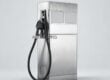
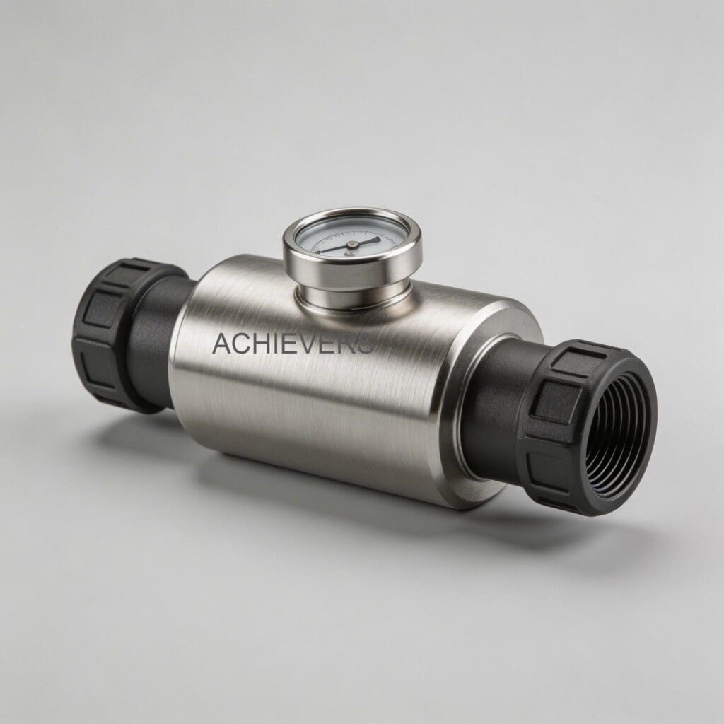
At their core, Oil Flow Meters are precision volumetric flow estimation instruments. Utilizing a robust oval gear design, these meters measure flow by passing an exact, discrete volume of liquid with every revolution. Because the internal moving parts are dynamically secured in tandem with the fluid volume traveling through the chamber, they maintain extreme accuracy over long periods of operation.
Available in line sizes ranging from 006mm (1/4 inch) to 150mm (6 inches), these meters are largely unaffected by outside factors caused by the installation geometry. The low pressure drop of the oval gear design allows them to excel in both gravity-fed and in-line pump applications. Depending on the pipeline stresses, vibration levels, and international standards (such as ISO, API, or ATEX requirements), buyers can specify these Oil Flow Meters with either standard inline (threaded) connections for compact integration or robust flanged connections for maximum structural integrity.
2. Head-to-Head Specification Comparison
Evaluating industrial oil flow meter specifications requires looking beyond internal mechanics to how the meter integrates with your broader piping network. The table below highlights the operational differences between threaded inline and flanged connection styles for oval gear Oil Flow Meters.
| Specification / Feature | Inline (Threaded) Connection Option | Flanged Connection Option |
| :— | :— | :— |
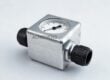
| Line Size Availability | Best suited for 006mm to 50mm (1/4" to 2") | Available across full range, ideal for 50mm to 150mm (2" to 6") |
| Pressure Drop | Low; highly efficient for smaller bore gravity systems | Ultra-low; optimal for high-volume pump discharge lines |
| Vibration Tolerance | Moderate; susceptible to thread galling over time | Exceptionally high; isolates meter body from pipe strain |
| Maintenance Accessibility | Requires pipe rotation or union fittings for removal | True drop-in/drop-out capability without disturbing adjacent pipe |
| Leakage Risk (High Temp) | Higher risk of micro-leaks due to thermal expansion | Minimal; torque-controlled gasket seals accommodate thermal shifts |
| Installation Footprint | Highly compact; fits tight mobile and skid layouts | Requires larger clearance for flange mating and bolt tightening |
| Strainer Integration | Provided with integrated mesh strainer | Provided with integrated mesh strainer; easier access to clean |
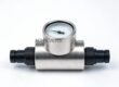
| Display Reading | Register top rotates every 90º for easy viewing | Register top rotates every 90º for easy viewing |
Quick ROI Snapshot
Opting for flanged connections on lines larger than 50mm typically requires a 15-20% higher initial hardware investment. However, by eliminating thread-sealant degradation and reducing meter removal time from 3 hours down to 30 minutes, the typical payback period is 12 to 18 months in high-maintenance industrial environments.
3. Application Comparison Table
Selecting the best oil flow meter for tank transfer applications or aviation refueling depends heavily on environmental and operational contexts. Use this matrix to match connection styles to your plant's specific fluid handling scenarios.
| Application Scenario | Recommended Option | Technical Reason |
| :— | :— | :— |
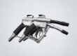
| Aviation Refueling Vehicles | Inline (Threaded) | Compact footprint, low weight, and handles intermittent mobile flows efficiently. |
| Heavy Fuel Oil Tank Transfers | Flanged | Flanges provide the structural strength needed for large diameter (up to 150mm) high-viscosity pumping. |
| High Vibration Pump Skids | Flanged | Distributes kinetic stress across the bolt circle, preventing the meter body from bearing the pipe strain. |
| Gravity-Fed Lubrication Systems | Inline (Threaded) | Low pressure drop oval gears easily handle gravity flow; threading is sufficient for low-pressure environments. |
| Hazardous Area (ATEX) Chemical Injection | Flanged | Zero-leakage priority; flanged gaskets provide a verifiable, standardized seal for volatile fluids. |
| Mobile Fuel Dispensing Depots | Inline (Threaded) | Rapid assembly/disassembly required for mobile skids; easily paired with flexible hoses. |
| Marine & Offshore Terminals | Flanged | Resistance to corrosive salt environments and shifting ship-to-shore pipe stress during high-volume batching. |
| Automated Recipe Control | Flanged | When paired with a Liquid Batching System, flanges ensure absolute zero air-ingress, protecting the 0.02% repeatability. |
Common Mistake to Avoid
Installing threaded inline meters on rigid, large-diameter pipe runs (>50mm) without expansion loops. Temperature fluctuations cause linear pipe expansion, turning the flow meter into a load-bearing structural component. This inevitably leads to threaded connection leaks and binding of the internal oval gears. Always use flanged connections or flexible compensators for rigid, thermally active piping.
4. Total Cost and Impact Comparison
To make an informed procurement decision, operations managers must look past the initial line item price. Below is a realistic operational cost comparison (using standard global USD multipliers) evaluating the lifetime impact of both connection types.
| Connection Option | Relative Purchase Cost | Installation Rework Risk | Typical Maintenance Intervention Time | Expected Life (Continuous Duty) | Best For |
| :— | :— | :— | :— | :— | :— |
| Inline (Threaded) | Base Price | High (thread tape/dope degradation) | 2 to 3 hours (requires pipeline disassembly) | 7 – 10 years | Compact OEM machinery, mobile skids, low-pressure loops |
| Flanged | Base Price + 20% | Low (standardized gasket torquing) | 30 to 45 minutes (drop-out design) | 15+ years | Heavy petrochemical, continuous process plants, high-vibration sites |
5. Decision Guide: Which One for Your Plant?
Still debating the optimal setup for your facility? Walk through these 8 operational scenarios to finalize your specification:
- You are handling fluids with rapidly changing viscosities: Choose Flanged. Oval gear meters instantly react when smooth movement starts and stops, measuring fluids of any viscosity accurately. Flanges prevent high-viscosity pressure spikes from stressing the connection.
- You operate an aviation refueling depot: Choose Inline. The simplicity of design, combined with sustained accuracy over long periods, makes inline threaded variants the historical standard for aviation refueling trucks globally.
- You have strict environmental emission limits: Choose Flanged. Threaded joints are notorious for micro-leaks over years of thermal cycling. Flanges with high-grade gaskets ensure compliance with stringent ISO and API environmental regulations.
- Your pipeline layout forces the meter into a tight, awkward space: Choose Either. The Achievers register top can be easily removed and rotated to every 90º orientation for display reading, making both flanged and inline models adaptable to tight spaces.
- You are building mobile diesel bowsers: Choose Inline. Smaller diameter piping (006mm to 25mm) on mobile equipment benefits from the lightweight, vibration-dampening nature of threaded connections paired with flexible lines.
- You need to monitor large diesel generators continuously: Choose Flanged. Engine rooms feature heavy vibration. Flanging your meter isolates it. (Consider adding a Fuel Consumption Meter on the return line for complete engine diagnostics).
- Your process requires frequent recalibration and auditing: Choose Flanged. The meter features a step-less calibration system that is consistent between calibration levels. Flanges allow you to quickly drop the meter out of line for laboratory proving without cutting pipe.
- You require automated additive injection: Choose Flanged. The automatic additive injector available on these models is best supported by a structurally rigid flanged network that eliminates pressure pulsations.
6. Best-Practice Installation Procedure to Prevent Leaks
Regardless of whether you select an inline or flanged meter, improper installation will compromise the meter's repeatable accuracy (better than 0.02%). Follow this systematic procedure engineered for industrial plant environments:
- Verify Specifications and Alignment: Confirm the line size (between 006mm and 150mm) matches the meter. Ensure the upstream and downstream pipes are perfectly axially aligned. Flow meters must never be used to pull misaligned pipes together.
- Purge and Flush the Line: Before installation, thoroughly flush the piping network to remove welding slag, scale, and thread tape debris. Oval gear meters are precision volumetric instruments; foreign debris will jam the rotors.
- Install the Integrated Strainer: Ensure the provided integrated mesh strainer is installed directly upstream of the flow meter. This is non-negotiable for protecting the dynamic moving parts.
- Position the Display: Determine the operator's line of sight. Remove the register top and rotate it (in 90º increments) so the Liter, US Gal, or UK Gal display is perfectly legible from the walkway.
- Execute the Connection (Flange/Thread):
- For Flanged: Insert appropriate gaskets. Hand-tighten all bolts, then use a calibrated torque wrench in a standard crisscross (star) pattern to achieve uniform seal compression.
- For Inline: Apply compatible liquid thread sealant (avoid PTFE tape, which can shred and enter the chamber). Thread carefully to avoid galling.
- Gradual Pressurization: Slowly open the upstream block valve to allow fluid to enter the chamber gradually. This prevents "water hammer" from slamming the oval gears into sudden, high-speed rotation.
- Perform Step-Less Calibration and Leak Test: Once operating at steady-state pressure, observe the connections for weeping. Utilize the step-less calibration framework to dial in the electronic or mechanical control accurately to your process fluid.
FAQ
Q: What is the exact repeatability of these flow meters?
A: Because the internal moving parts are dynamically secured in tandem with the volume of fluid, repeatability is guaranteed to be better than 0.02% across consistent calibration levels.
Q: Will installation geometry or pipe elbows affect the meter's accuracy?
A: No. Because these are positive displacement (volumetric) oval gear meters, they are not affected by outside flow profile components caused by the installation geometry. They do not require straight pipe runs upstream or downstream.
Q: Are these meters capable of measuring intermittent or trickling flow?
A: Yes. The meter instantly moves when there is smooth fluid movement and immediately stops when the movement stops, making it highly capable of measuring intermittent flows and very low flow rates.
Q: How do we handle maintenance if the meter gets jammed with debris?
A: The units are specifically designed for quick and easy maintenance. The integrated mesh strainer catches most debris, but if cleaning is required, the internal gears can be accessed quickly. Standard spare parts are widely available.
Q: What units of measurement do the registers display?
A: The calibration displays are available in Liters, US Gallons, and UK Gallons, making them suitable for distribution depots worldwide. Electronic control outputs are also available.
Q: What kind of warranty supports these industrial units?
A: Achievers provides a standard 1-year warranty on these flow meters, with an optional 2-year extended warranty available on demand to secure your capital investment.
Q: When is the best time to buy oil flow meters for manufacturers upgrading their plants?
A: The ideal time to upgrade is during planned preventative maintenance turnarounds or when transitioning from gravity-feed to automated pumping systems, ensuring you can standardise your flange sizes without unscheduled downtime.
Upgrading your fluid handling infrastructure requires precision instruments built for your exact site realities. Whether you are dealing with tight skid footprints requiring threaded connections, or high-pressure, high-vibration environments demanding heavy-duty flanges, Achievers Pumps and Valves has the engineered solution. Contact our technical engineering team today with your required product name, expected flow capacity, target application, and specific site conditions to receive a tailored, consultative sizing recommendation.