When a fluid handling system starts exhibiting sudden pressure drops or pulsating flows, the financial impact extends far beyond the cost of a replacement part. In global continuous-process environments—whether you are operating an offshore petrochemical platform, an aviation refueling terminal, or a commercial food and beverage plant—undetected flow discrepancies mean compromised batch quality, overflowing tanks, and lost revenue.
Accurate fluid measurement relies on stable, predictable mechanical operation. If your meters are drifting or surging, jumping to order a replacement without diagnosing the root cause often guarantees the new meter will suffer the exact same fate. This guide provides an expert-level framework for oil flow meters erratic readings causes and fixes, equipping industrial engineers and plant managers with the troubleshooting steps necessary to identify pipeline issues, fluid shifts, and mechanical wear before they escalate into full-system shutdowns.
Quick ROI Snapshot: Proactive Meter Troubleshooting
- Typical payback period: Immediate (saves replacing a functional $2,000+ meter)
- Downtime reduction: 4-6 hours saved per incident by utilizing structured field diagnosis.
- Yield improvement: Reclaiming even a 0.5% accuracy drift on high-volume mineral or furnace oil lines can save thousands of dollars monthly in unaccounted product.
1. Quick Reference: How Oil Flow Meters Work
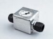
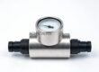
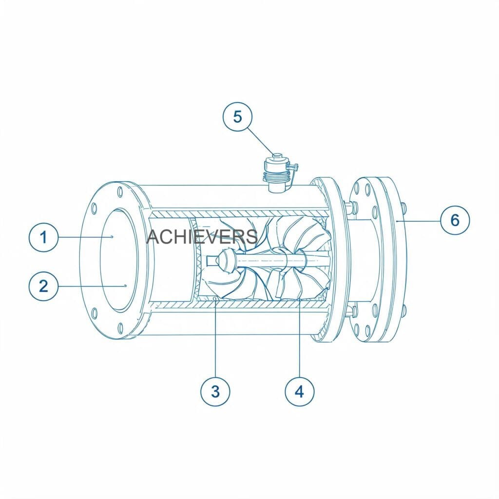
To troubleshoot effectively, you must first understand the fundamental physics of the instrument. The most robust industrial flow meters rely on a positive displacement, oval gear design.
Unlike velocity-based meters (such as turbine or ultrasonic), volumetric oval gear meters measure flow by trapping and passing a precise, finite volume of liquid with every single revolution. As the fluid enters the meter chamber, the differential pressure causes the interlocked oval gears to rotate. Because the internal moving parts are dynamically sealed and locked in tandem with the fluid volume, the meter instantly moves when there is fluid motion and instantly stops when the fluid stops. This allows the instrument to accurately measure intermittent flows, low flow rates, and high-viscosity fluids without requiring straight pipe runs upstream.
Understanding your meter's baseline specifications is crucial before assuming the unit is out of calibration. Below are the standard operational parameters for Achievers' precision-built meters:
| Specification Parameter | Technical Details | Operational Impact |
| — | — | — |
| Measurement Principle | Volumetric Positive Displacement (Oval Gear) | Highly immune to upstream flow profile disturbances. |
| Line Size Availability | 006mm to 150mm (1/4" to 6") | Scalable from lubrication lines to main terminal offloading. |
| Accuracy & Repeatability | Better than +/- 0.02% repeatability | Ensures absolute consistency between calibration levels. |
| Pressure Drop | Ultra-low pressure drop design | Ideal for both gravity-fed and in-line pump applications. |
| Display / Register | Removable, 90º rotatable top register | Allows flexible installation orientations without losing readability. |
| Filtration | Integrated mesh strainer | Protects tight-tolerance internal gears from damaging particulates. |
| Fluid Compatibility | Mineral, vegetable, hydraulic, furnace, heating oils | Handles wide-ranging viscosities without recalibration needs. |
2. Troubleshooting Matrix
When encountering anomalies, cross-reference your site observations with this diagnostic table. Many symptoms that appear to be meter failures are actually pipeline or fluid conditioning problems.
| Symptom | Likely Cause | Diagnosis Steps | Fix |
| — | — | — | — |
| Pulsating flow with mechanical knocking | Entrapped air or gas pockets in the fluid line. | Check upstream piping for leaks. Monitor pressure gauges for rapid fluctuation. | Install an air/gas eliminator upstream of the meter. Tighten all suction-side flange seals. |
| Erratic or jumping display readings | Gear slippage due to sudden viscosity drop or flashing. | Measure fluid temperature. Verify process operating temperature is within meter specs. | Stabilize fluid temperature. If handling volatile fluids, increase backpressure to prevent flashing. |
| Zero flow registered despite pump running | Sheared coupling, jammed rotors, or blocked strainer. | Isolate meter. Open integrated strainer housing. Attempt manual rotation of gears. | Clean integrated mesh strainer. Replace sheared coupling or damaged rotors if hard debris entered the chamber. |
| Sudden, severe pressure drop across meter | Severe fouling or partial blockage in the measuring chamber. | Install differential pressure gauges across the meter. Inspect fluid for heavy sludge/particulate. | Flush the system. Perform a complete breakdown and solvent cleaning of the oval gears and chamber. |
| Slow, progressive accuracy drift (under-reading) | Gradual mechanical wear of oval gears or chamber walls increasing internal slippage. | Perform a proving run with a known volume. Inspect gear clearances with feeler gauges. | Utilize the step-less calibration system to adjust. If wear is excessive, replace the oval gear set. |
| Output signal loss (Digital versions) | Corroded terminals, severed cable, or failed pickup coil. | Check wiring continuity with a multimeter. Inspect terminal box for moisture ingress. | Reseal terminal box. Replace damaged wiring or faulty magnetic pickup sensor. |
| Fluid leakage at the meter body or flange | Degraded O-rings/gaskets, or over-pressurization. | Clean meter body. Run system at pressure and visually trace the leak origin. | Replace body O-rings and flange gaskets. Ensure system pressure relief valves are functioning. |
| Unusually high operating noise (whining) | Cavitation due to restricted inlet or insufficient Net Positive Suction Head (NPSH). | Check upstream valves are fully open. Measure inlet pressure. | Fully open isolation valves. Clean upstream Y-strainers. Ensure feed pump is not oversized. |
| Register display unreadable or fogged | Moisture trapped under the register glass or chemical attack on the lens. | Inspect the environmental seal on the register cap. | Remove the register top, clean the glass, replace the environmental sealing gasket, and reassemble. |
| Valve/Pump not responding to batch signals | Broken linkage or failed preset micro-switch in the mechanical/electronic control. | Manually trigger the batch preset. Test the switch continuity during operation. | Calibrate the batching linkage. Replace the faulty micro-switch. |
3. Step-by-Step Field Diagnosis Procedure
When a flow meter drops offline or loses accuracy, structured field diagnosis prevents unnecessary factory returns. Follow this standardized procedure before removing the Oil Flow Meters from the pipeline.
Required Tools: Lockout/Tagout (LOTO) equipment, spill containment kit, calibrated multimeter, pressure gauges, standard metric wrench set, non-abrasive solvent, feeler gauges.
- Secure the Process System: Perform LOTO on the associated supply pumps. Close the upstream and downstream isolation valves to isolate the meter completely. Place a spill tray beneath the meter to catch residual fluid.
- Depressurize and Drain: Safely bleed off any trapped pressure using the vent valves. Slowly open the meter's drain plug or carefully crack the flange bolts to drain the remaining oil into a safe container.
- Inspect the Integrated Mesh Strainer: Access the strainer housing before touching the measuring chamber. 90% of sudden pressure drops are caused by a fouled strainer. Remove the mesh, clean it with an industrial solvent, and inspect for metallic shavings (which indicate upstream pump wear).
- Assess Mechanical Freedom (Rotor Spin Test): Remove the front cover plate of the measuring chamber. Using your fingers (wear appropriate PPE), attempt to rotate the oval gears. They should turn smoothly with minimal resistance. If they are jammed, do not force them.
- Check for Chamber Scoring: If the gears rotate but feel gritty, remove them carefully. Inspect the internal chamber walls and the gear faces for deep scratches or scoring. Heavy scoring allows fluid slippage, permanently destroying the meter's 0.02% repeatability.
- Evaluate the Electronic / Register Linkage: For mechanical registers, inspect the drive gear and packing gland. For digital units, use your multimeter to test the pulse output. Wave a metallic tool near the pickup coil to simulate gear teeth movement and verify the control system receives the signal.
- Perform a Zero/Span Calibration Check: If the meter is mechanically sound and the electronics function, the issue is likely calibration drift. Reassemble the meter, re-pressurize the line, and dispense a strictly measured volume into a certified proving tank.
- Adjust the Step-less Calibration: Compare the registered volume to the physical proven volume. Use the step-less calibration mechanism to dial the accuracy back into the acceptable +/- 0.02% window.
4. Installation and Setup Errors That Cause Ongoing Problems
Even the most robust positive displacement Oil Flow Meters will fail if installed contrary to fluid dynamic principles. Plant engineers frequently inherit poorly commissioned systems. Below are the most common installation errors, their resulting symptoms, and how to permanently correct them.
| Installation Error | Resulting Symptom | Necessary Correction |
| — | — | — |
| Mounting without an upstream strainer | Jammed rotors, sudden system failure, torn internal seals. | Install an integrated mesh strainer or an external Y-strainer immediately upstream. |
| Installing meter at the highest point in the pipe | Erratic readings, air lock, and over-registering of flow. | Relocate the meter to a lower section of piping to ensure it remains full of fluid at all times. |
| Omitting an air eliminator on gravity drops | Meter registers "phantom flow" as air pockets pass through the rotors. | Install a mechanical air/gas eliminator before the meter, especially in tank offloading applications. |
| Register orientation forcing awkward viewing | Human error in manual batch reading; ignored display warnings. | Utilize the removable register top; unbolt and rotate it 90º so the display directly faces the operator. |
| Piping stress transferred to the meter body | Flange leaks, chamber distortion, and gears binding under pressure. | Install proper pipe supports and expansion joints on both sides of the meter to bear the pipeline weight. |
| Inadequate backpressure on volatile fluids | Fluid flashes into vapor, causing severe cavitation and whining noise. | Install a backpressure valve downstream to keep system pressure above the fluid's vapor pressure. |
Common Mistake to Avoid: Bypassing the Strainer to "Increase Flow"
Operations managers often mistakenly remove the internal mesh strainer to reduce the pressure drop and speed up tank transfer times. Do not do this. Oval gear flow meters operate on microscopic internal tolerances to maintain high accuracy. Bypassing the strainer guarantees that welding slag, pipe scale, or degraded pump seals will enter the measuring chamber, locking the gears and causing catastrophic, non-warranty equipment failure.
5. Preventive Maintenance to Avoid Recurrence
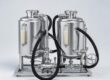
Reliability in fluid transfer—whether it is vegetable cooking oil or heavy furnace oil—depends heavily on proactive maintenance. Adopting a strict PM schedule not only extends the operational life of your instruments but also protects downstream equipment like your automated Liquid Batching System or specialized Fuel Dispensers.
Monthly Checks:
- Visual Leak Inspection: Check all flange connections and the main cover seal for weeping oil. Tighten bolts to specification.
- Acoustic Profiling: Listen to the meter during standard flow. A smooth, rhythmic clicking is normal. Grinding or high-pitched whining indicates impending bearing failure or cavitation.
Quarterly Checks:
- Strainer Blowdown: Isolate the meter and thoroughly clean the integrated mesh strainer.
- Accuracy Proving: Run a set volume through the meter into a calibrated prover can to verify the repeatability remains better than 0.02%.
Annual Maintenance:
- Seal Replacement: Replace the main body O-rings and any dynamic seals around the register linkage to prevent slow environmental leaks.
- Internal Tolerance Check: Open the measuring chamber during a scheduled plant shutdown. Inspect the oval gears for wear and check the step-less calibration system for proper engagement.
6. When to Call Service vs. Fix Yourself
While the straightforward design of oval gear meters makes them highly serviceable, knowing when to escalate to an industrial oil flow meters supplier or the OEM is critical for maintaining site safety and international compliance.
What you should fix in the field:
- Clogged strainers and dirty filters.
- Minor calibration adjustments using the step-less calibration tool.
- Replacing external terminal wiring or blown fuses in the digital display.
- Rotating the register top for better visibility.
- Replacing standard flange gaskets and external O-rings.
When to contact the factory (Return to Manufacturer):
- Deep Chamber Scoring: If hard debris has gouged the internal measuring chamber, the meter cannot simply be polished in the field. It requires factory re-machining and recalibration.
- Explosion-Proof/ATEX Certification Compromise: If a meter operating in a hazardous area (e.g., aviation refueling or petrochemical zones) suffers damage to its intrinsically safe housings or potted electronics, field repairs will void its safety certification.
- Total Gear Seizure: If the oval gears have cold-welded or seized to the central shafts due to chemical incompatibility or extreme overheating, specialized press tools are required to rebuild the unit.
FAQ
Q: Why does my oil flow meter reading fluctuate wildly when the pump starts?
A: This is almost always caused by air entrapment in the empty pipeline rushing through the meter ahead of the fluid. Ensure the piping remains flooded, or install an air eliminator upstream to vent the air before it reaches the measuring chamber.
Q: Can I use the same meter for both light hydraulic oil and heavy furnace oil?
A: Yes. Positive displacement meters excel across varied viscosities. However, if the viscosity shifts drastically, you may notice a slight change in the pressure drop and a minor shift in the slip profile, which might require a quick adjustment using the step-less calibration system for absolute precision.
Q: What is the standard lifespan of the internal oval gears?
A: With properly filtered, clean lubricating fluids like mineral oil, the gears can easily last 7 to 10 years without requiring replacement. Abrasive fluids or bypassed strainers will reduce this lifespan to months.
Q: Our site is operating under tight global safety standards (ISO/CE). Does field maintenance void the warranty?
A: Achievers designs its meters for "quick and easy maintenance." Routine tasks like cleaning the integrated strainer, calibrating the unit, or rotating the register will not void the warranty (which is 1 year standard, 2 years extended). However, modifying the meter body or replacing OEM parts with third-party components will.
Q: Is it normal for the meter to induce a pressure drop in my gravity-fed line?
A: Every mechanical meter induces some pressure drop, but Achievers meters feature a specifically designed low pressure drop ideal for gravity applications. If the drop is severely restricting your flow, the internal strainer is likely clogged and requires immediate cleaning.
Q: When researching oil flow meters troubleshooting in India or other high-temperature regions, does ambient heat affect the display?
A: High ambient heat combined with humidity can cause condensation under the register glass if the environmental seal is degraded. The mechanical measurement remains accurate, but you should replace the register sealing gasket to restore display clarity and protect the internal linkage.
Q: My meter measures perfectly in liters, but we need to switch our global reporting to US Gallons. Do I need a new meter?
A: No. The meters are available with Liter, US Gal, and UK Gal alignments. The electronic displays can typically be reprogrammed, and mechanical registers can be swapped out by the supplier without removing the primary measuring chamber from the pipeline.
If you are experiencing persistent flow anomalies, struggling with batching inaccuracies, or planning to upgrade your fluid handling infrastructure, expert guidance ensures you get the exact specifications required for your process. Contact Achievers Pumps and Valves today with your desired flow capacity, fluid application, and site conditions, and our engineering team will help you select, troubleshoot, or optimize the perfect metering solution.